Comfort of life of a modern person directly depends on the availability of reliable source of electrical energy. On it is tied almost everything - lighting of premises, cooking and storage of food, heating of premises and heating of water, air conditioning and ventilation, means communication and access to information, dozens of other devices and devices without which it is already difficult to imagine its Existence.

Posting in the apartment with your own hands
Electricity providers in our time work stably, without serious and the long crashes , and if the consumer pays for services in a timely manner, he can expect full access to the available "benefits of civilization".But only power supply companies guarantee the supply of voltage to the "watershed" - to counter consumed energy. And then begins the zone of responsibility of the owner of housing, and in his right to arrange all points of lighting and connection to the power grid in the optimal amount, from his point of view, and in an easy-to-use place. But how to approach the solution
of this question? Will the wiring in the apartment be assembled by myself, or is it more expedient to use the services of electricians?
Will the owner of the apartment independently optimally place and calculate all the elements of the domestic electricity network?
Unequivocally this question can not be answered. Much depends on the preparedness, "savvy" of the apartment owner in the field of physics, electrical engineering. An important factor is the ability to long-term planning, since the work on the replacement of wiring is implied for many years forward .And, in the end, the owner of the apartment should have a good baggage of skills and in the field of construction works - without this, too, will not cost .

The laying of the wiring is a significant component of the general construction works
The purpose of this publication is to give the apartment owner an idea of the scale of the measures for laying the domestic electricity network, about basic principles its planning, the correct distribution of loads, receptions installation of the cable part and electromotive products, about other important nuances. There will be an opportunity to understand, whether it is worthwhile, to undertake such a volume of works independently, or still invite qualified masters. From the point of view of professionals, without the practice and without the electrical safety permit, it is better not to perform such work independently, because there are a lot of nuances that are simply impossible to describe on the scale of one article - their knowledge comes with many years of experience. However, , know basic principles laying wiring in the apartment will useful to any owner - it will be possible to monitor the work of the masters( alas, there are among them rascals), and for safe housing exploitation such an understanding of the matter never will superfluous.
When is it worthwhile to install a new wiring in the apartment?
Content of the article
- 1 When is it worthwhile to start laying new wiring in the apartment?
- 2 Basics - planning the home electricity network
- 2.1 Video: Tips for planning the apartment power network
- 3 Wiring methods in the apartment
- 3.1 Video: the option of laying wires on the walls of the apartment
- 4 We are continuing the drawing of the
- 5 circuit Which section of the wires are needed for laying?
- 5.1 Video: basic concepts of self-installing apartment wiring
The one who received the new apartment in the houses that were built and surrendered according to the old principle - "turnkey" ( although, as a rule, with not very high quality), knows how, is often , uncomfortable, ill-conceived there werethe points of connection to the mains are placed. Yes, everything corresponded to the old GOSTs, but the trouble is that these standards were written when the saturation of human life with various electrical appliances was significantly different from the current conditions.
As the new devices are purchased, the has to extend the extension or even to install new lines, as some electrical installations obviously do not have enough for the calculated power of old wires. Pulling on LAMs cables - this is the sensation of a particular dyslex , and an obvious minus the interior decoration of the room.

Extra extensions on the floor never paint the interior of the
Moreover, with insufficient connection points, many tenants who are poorly versed in electrical engineering sometimes perform unimaginable connections using tees, using even them in several cascades. Alas, this is a direct road to the occurrence of a fire hazard situation in the apartment.

And here it is already - the direct way to the big trouble
And now, when sooner or later it comes time to make a capital reminder nt in the apartment, the most reasonable step is completely, from the point of the input and to the last outlet,wiring, and the entire electromotive part, having planned the installation of power supply points is most convenient, rational and safe.
There is also still one very important reason ever completely change the cable part. The fact is that when building high-rise buildings in the old days, for reasons of economy, the internal wiring was mostly made of aluminum wires. Aluminum has like and good conductivity characteristics, but now it is practically not used for these purposes, because its disadvantages significantly outweigh its advantages.
- Firstly , the metal is very soft in itself. It is easily deformed, pressed through the use of contact screws, terminal washers and , .- two times in one place to make a contact kt time whether it will turn out - the wire will just break in thinned place. That eats, repair work with aluminum wiring is extremely difficult. It's very difficult to , and it will be extremely irrational to use such technology in the conditions of home wiring installation.
- However, aluminum is plastic only when it is, say, "fresh."This metal has an amazing property - the electrochemical processes occurring in it when passing current, with the passage of time radically change the properties of matter. After 15 ÷ 20 years of operation( and for a wiring - it's quite a short time), aluminum conductors become brittle. It is possible that sudden network breaks, practically , are uncaused, which can be very difficult to find, and to eliminate is more difficult, because the wire can break even with cautious attempts to make a new twist or bend it for the terminal connection.

The old aluminum twists reliability, alas, do not differ
- Another one striking property: it would seem, very corrosion-resistant metal, but that's not it! If even a small amount of water has entered the conductor, the processes of electrocorrosion are inevitable under the influence of electricity. And , they can be invisible externally - in appearance, the entire conductor inside can be "corroded" so much that even a small load causes to heat , spark or failure. Sometimes any touch to such a wire leads to its breakdown.

Compare with the picture above - is there a difference?
In other words, if the deal with the Electrofacilities seriously , then do not hesitate to replace all the old aluminum wiring on on reliably copper. Electrical parameters in her even higher plasticity - a good( but not excessive), and does not change any of time, any of operating under heavy loads. The cost of copper wires is certainly much higher, but the wiring in the apartment is done, as already mentioned, for decades forward , and it's simply unreasonable to save on such issues. At the same time with the replacement, you can simultaneously solve all the problems with the optimization of the placement of all elements of the home electrical network.
If the owner acquired new apartment, in a house that was put on a "do it yourself", there is nothing to think - you need to carefully plan the entire apartment grid with considering his vision location appliances and furniture in the rooms and do the wiringliterally in the first place - still before pouring floors, finishing walls and ceilings . Below in the text it becomes clear why this is so.
Still several arguments in favor of not modernization or repair, but a major overhaul of the old wiring.
1. In the old days, the grounding circuit in residential buildings are not considered mandatory, and all the in-house network are routed through the system TN-C , when the working and ground zero were wound on a single conductor( PEN) still at an electrical substation. The only advantage of this approach is the simplicity of installation and minimal material consumption, since all the sockets in the apartment were entangled only by two wires - zero and phase.

System TN-C - "the day before yesterday" of electrical engineers
When a reset or breakdown on the metal case of electrical appliances is very likely appearance of life-threatening voltage. Moreover, this type of contact connection, not the , gives the the correct operation of the residual current devices( RCDs), some modern pulse power supplies. Today, this system is not used, somewhere - even prohibited by law, and it be sure to change to one of the more advanced systems: TN-S or TN-C-S .
TN-S is more often used in private homes in which the own earthing system is organized. Although, they can also be used in apartment buildings to organize earthing tires, connected by welding and passing from the external ground loop to all floors.

Est TN-S
system diagram Yet more frequently in high-rise residential buildings, a system TN-C-S , wherein gluhozazemlonnaya neutral section on at two conductors - working zero and the grounding circuit, directly in driveway distributionshield.

The TN-C-S
principle is often used in multi-storey buildings. In any of the last two cases three contacts are already used for wiring: phase, ground and zero. One can immediately mention the color marking of these wires - one must comply with the current standards.

Color coding for AC wires
Please note that the color of the phase wire may vary. But here is zero and grounding - they have mandatory coloring, so that its could not be confused when conducting electrical work.

Several phase conductors can be enclosed in one cable
By the way, several phase conductors can be enclosed in one cable. They will differ in color, but with all two wires will be marked with their mandatory coloring - "working zero" and "ground".
Many modern electrical appliances are equipped with a three-pin plug. So, it is necessary to make an important explanation. When installing new outlets, the owners of , of course, try to install also three-pin. However, if you do not have wiring in TN-S or TN-C-S in your apartment, you should never make a jumper between the zero contact and the grounding directly on the socket.

If the life and health of your loved ones are not indifferent to you, never do this "grounding"! !!
What can be done at the level of the switchboard - is absolutely inadmissible directly at the connection point. This will not only not give the desired effect, but also sharply increase the level of danger. The probability of electric shock or the occurrence of a fire hazard situation with such a connection is huge! Better in general not have a connection to the ground, than to organize like.
And more better - mount new wiring by all rules!
2. The second important argument is that the very principle of wiring used earlier in residential construction is extremely imperfect. 's speech goes to about the so-called "dosing" of the load. To understand - remember the old distribution boards. Electric meter, two machines( or fuses - plugs) - and all. Two wires walked into the apartment, were lost somewhere in the thickness of the wall, and from them they were made in contact boxes of a branch to each lighting point or outlet. In a word, thin branches branch out from the trunk of the tree, so the layers were removed from the main wires. Again: the view of economy is profitable, but in all rest - does not stand up to criticism.
This system literally swarms with twists on every branch, and any excess wiring is always a vulnerable place of posting. If necessary, to de-energize one of the rooms, it was necessary to disconnect the power in the entire apartment. Even a minor accident, an accidental AS on one of the branches led to the disconnection of the entire apartment network. Well, if something happened serious ( breakage or burning of the cable, hidden in the wall), then the search for an emergency site and the carrying out of repair work turned into a very complicated problem.

Approximate distribution of the domestic electricity network to the
zones This can be easily avoided by organizing the zoned wiring system - from the entry point, that is, from the apartment switchboard, separate power lines with the required wire section corresponding to the load are laid in the each room, on each high-capacity electrical appliance, on each group of sockets or lighting. Yes, of course, you will need much more cable here, but the home electrical network will become convenient and safe to use, it will easily be amenable to the necessary modernization or repair.
Basis Basics - Planning a Home Power Supply
So, the first stage in any case - will there be a major overhaul of the . or wiring will be laid in a new apartment, always goes drawing up a scheme of the apartment power network. And it's best to do it yourself - none other than hosts can not do it better.
Perhaps someone doubts their ability to conduct such planning. It's nothing to worry about - we do not need to hurry, we do everything consistently, step by step. And you will see that this is not so difficult at all.
To begin with, you need to prepare a plan for your apartment. There can be several options. First, you can make a copy of the technical passport. Secondly, it is true that mu mu does not . It should be easy to draw an approximate scheme( best of all, of course - on a scale) on a regular sheet of paper. Third, , if desired, , you can find a standard project of the house in which the apartment is located.(Such document can be in , another operating or design organization.) It is possible that will come to the aid of ).And fourth , modern computer engineering applications( CAD ) allow you to quickly and accurately execute the desired drawing .
For an example of we take diagram of one-room apartment, executed literally in 10 minutes in САD .The procedure for planning the residential network network with a different number and arrangement of rooms does not change - principles remain the same.

The apartment layout that is completed in CAD
for several minutes In this case, Room 1 is combined bathroom, Room2 - entrance hall, Room3 - kitchen and Room4 - living room.
Not bad even have variants t t such a drawing and with the dimensions affixed: it will then be easier to determine the required number of cable products.

The same drawing - with the dimensions on the
scale In order not to be afraid of the error and some accidental damage to the drawing , you can print to yourself not to the printer, or to make a copy in with the necessary quantity - for drafts, taking as a basis for the beginning ""Scheme - only the walls, windows and doors.

The initial "clean" scheme - with it and will begin to work
Now we need to imagine how in this area will be placed the available furniture items and electrical appliances for various purposes. There is no need to hurry - it is necessary to take into account not only what has already been acquired and is waiting for the installation, but also the planned novelties in the future at least for 5-10 years. For example, children grow up, and already through a couple of years in theirroom will need to put a desk with a lamp, computer, TV and .In the living room in the future plans to install modern climate equipment( air conditioning or convectors), and in the kitchen sooner or later the hostess will want a dishwasher and a multifunctional oven.
Moreover, it is necessary to arrange all these pieces of furniture and household appliances in the places where they, with certain to the assumption of admission, will be installed. A very awkward situation will happen if, after completing the laying of the new wiring, after only a short time, the will have to get the old extensions! Why then were all these repair torments?
Probably, it will be reasonable to hold an "extended family council" in this regard, in order to come to a common opinion on interior design and filling of premises. And now we turn again to the drawing - we begin to "arrange" everything in places. Special principles on conventional symbols here can not be achieved - this scheme is working. The main thing is to number all the items and devices, take them to the description - the table, and it is desirable - to highlight on the diagram those that require mandatory connection to the power source, for example, shading the other color( in the example for the scheme - highlighted in red).
So, by rooms:

Virtually "arrange" everything in its place
In the living room:
1 - folding sofa bed .
2 - bedside table with night light and point of connection, for example, a charger for the phone.
3 - air conditioning - split system .
4 is a plasma TV with sound system "home theater", with receivers or other digital television equipment.
5 - dining table with chairs.
6 - cabinets.
7 - work area with computer and peripherals.
Those points that require connection can be identified in the text.
In the kitchen:
8 - refrigerator.
9 - dining table with chairs.
10 and 11 - working tables ( worktops ) on which can be stationary or intermittently kitchen appliances - microwave, multivark, combine, blender, electric kettle and others.
12 - electric stove with oven.
13 is a sink.
14 - dishwasher.
In the bathroom and WC:
15 - washing machine.
16 - boiler.
17 - washer with spot light and a point of connection of a hair dryer.
18 - toilet seat.
19 - bathroom.
In the hallway:
20 - cabinet with additional dot illumination.
So, the main "consumers" on the scheme are highlighted. It is clear that you need more and backup sockets( for example, turn on the iron, vacuum cleaner, other small household appliances) - their placement can also be envisaged, so that they are not uselessly located behind the massive pieces of furniture.
You can immediately place the location of the outlets on a separate blank "blank".
You can, of course, use any conventions that are understandable to you. But if the owner wants his design to become clear to a specialist and an electrician, then it's better to apply the badges adopted in the professional environment. All of them know - does not necessarily have , it will be enough to be the most basic. For example, those listed in the table:
| Symbol | What is in the diagram |
|---|---|
 | Power shield |
 | Energy consumption meter |
 | Single pole safety device |
 | Two-pole circuit breaker |
 | |
 | |
| | Socket with protective earth contact, for concealed installation |
 | Socket double, with protective earthing contact, for concealed installation |
 | Three-pole socket, with protective earthing contact, for open installation |
 | Two-pole socket outlet, with protectivegrounding contact, increased moisture resistance( IP44 - IP55) |
 | switch-Key switch |
 | dvuhklavishny |
 | unit - two switches and socket concealed installation |
Thus, in Scheme post sockets:

To begin with, we are determined with the
sockets Now it's time to think about the lighting points. They can be placed in the center of the room( that's when you need dimensions on a scale), and in random order, making the accent light in one direction or the other, or organizing several backlighting points( tiers).In our case, place the lamps in the center of the rooms. And immediately note places for switches. They are usually located inside the room( except for bathrooms and, sometimes, kitchens).A typical installation site is near the door, from the side of the castle. Although - it's not a dogma at all, the owner can determine the most convenient place himself, in his opinion. For example, you can place a block of switches in the hallway, which will be used to illuminate the corridor itself, the bathroom and even the kitchen.

Then, "suspend" the fixtures and arrange the switches
With the placement decided, now it is necessary to proceed to planning the route of laying the wires. Here various options are possible, depending on the degree of readiness of the premises in terms of construction of , from of the planned ways of finishing, from of the location of the input to the apartment, from the preferences of the owners themselves.
Video: Advice for planning the residential network
Wiring methods in the apartment
Just make a reservation - only apartment options, that is, with concrete or brick walls, will be considered. If someone needs information about the electrical network in the wooden house , then he can get her in the corresponding publication of our portal.
So, what acceptable ways of laying power cables are used in the apartment conditions:
A. If the walls are in the "draft" version, and in the future they are planned to be covered with a layer of plaster or lined with plasterboard, the wiring can be placed directly over the existing surface in corrugatedplastic pipes( if allows the thickness of the future finishing layer) or simply in an open condition, provided that the cable has reliable double or triple insulation .

The wires can simply be fastened to the aspiring walls of the
Video: Variant nt pr wire strips on the wall of the
apartment B. If the plaster layer on the walls is already applied to the , or it is planned too thin, not the capable to close the cabling, then will have to make shrouds in the wall for laying wires in them.
The case is , of course, very tedious and dusty, but it can happen, and nowhere else - this approach often remains the only option. When laying wires in such shrouds , they are fixed in them either with gypsum with locks , or with special plastic dowels, inserted into drilled for them holes.

The wire can be fastened in a shroud with a special bracket. ..

. .. or simply gypsum "bumps"
Shtroby can not be cut in completely arbitrary places. There are certain rules for this defined rules - there are zones near the window and door openings, external and internal corners, near the gas mains where the shrouding and cable laying are inadmissible. The graphic information for this account is - on the of the given below:

Typical locations for the

electrical paths Several more rules for laying the wires in the
Be sure to pay attention to one important detail. All hidden gaskets to the outlets and switches from the distribution boxes must be kept vertically. It is explained very simply - so it will be easy to trace the route of plastered wire without any special devices.

And so to do - is strictly prohibited
No bends and turns, no " on straight" at an angle should not be. Do not hope, say "I will remember."This is very quickly forgotten, and, besides , another person can try to drill a hole or drive a nail. End this can very sad.
When laying cables in shrouds it is necessary to have its arsenal still and a bit for perforator which will be required for cutting jacks under for socket and distribution( jacking ) boxes.
Now let's talk about the main sections, which will be laid wires from the switchboard to the mounting boxes.
1. The first option is exactly also , as described above, that is, horizontally along the top edge of the wall, in the shtrobe or in the of the .Option - extremely time consuming and expensive - for example, to bring power to the outlet on the opposite end of a large room it will be necessary to skirt all corners - the cable will leave very much.
2. If and still have floor screeds in the new or overhauled apartment , it is possible to lay the pipes in plastic or metal pipes according to overlapping surfaces. Here it will be possible to lay the routes to the junction boxes of with the shortest by .In the future, the screed or other floor covering will completely hide these cable pads.

Very convenient option can be laying wires on the floor, before pouring the screed

So it may look like in the branched household electricity network
By the way, with this "lower" location of the apartment wiring in some cases, you can in general do without making shrouds or to reduce thisoperation to a minimum. For laying wires in such situations, special electrical plinths are often used, on which there are already installed sockets.

Electrical plinth with sockets
And this - still is not all. A new trend is widespread: special kits that include electrical skirting boards , cable channels , junction boxes, sockets and switches, other electromotive products.

Kit for laying wiring - everything has been thought out, to the smallest detail
Certainly, this approach is not applicable to all styles of decoration, but it also has a right to exist. And, incidentally, it enjoys constantly growing demand, since it minimizes dirty and complex construction work to a minimum.
3. Another option that helps significantly reduce the consumption of wires is the use of the ceiling surface for laying the main routes. This, of course, does not eliminate the need to make shrouds for laying wires on the walls and jacks for the installation of sockets and boxes. But in the from the switchboard and up to the mounting boxes, the wires can be fastened in the corrugation to special clips directly to the ceiling, laying trails along the shortest distance. By the way, absolutely nothing prevents from placing itself boxes on the plane of the ceiling( although it will not be easy to get to them then, if needs any repair or adjustment work).

The ceiling is an excellent place for wiring. Of course, subject to its further decorative finish
True, all this will be possible only if it is planned to install a suspended or stretched ceiling, which will hide the cabling. In other words, if it is possible to mount a suspended or stretched ceiling - it is necessary to agree to agree - the mass of electrical problems simply "dissolve". As a last resort , it is quite realistic to think of some original hanging structure along the wall in which it will be possible to hide the padded wires.

In such a box, you can hide any wiring of
. Continue drawing up the
circuit. Let's return to again to our scheme - the points where the power supply must be switched on are already marked on it, but the tracks have not been laid yet by the .It's time to do it.
The reader is probably already understanding the way the trunk lines are laid, and with reference to his apartment he will be able to decide whether it will be a wall gasket or that can be traversed in some sections along the shortest path if a floor or a flow plane is used.
In our example, the tracks will be conducted along the walls.
So, in each room should have its own mounting box( at least - one).It is located, as a rule, near from the entrance of the line from the switchboard to the room. It is more advisable to place the bathroom box in the corridor, so that the contact connections in it are not exposed once again to the increased humidity.
In the diagram, let's mark the junction boxes with orange circles.

We continue drawing up the scheme - we plan the location of the
mounting boxes. We begin to "pull the wires" to each box from the outermost sockets. A loop, that is, in series, it is better not to have a power outlet - there can be voltage drops on the far, if those that are closer to the box are reset. Better not to stint and lay to each own cable.
By the way, if the sockets are placed "coaxially" from two sides of the of one wall, they can be connected with wires coming from of one box and ( ) on located in one shtrobe .living room and kitchen).Of course, this will make it possible to save money on the gasket .In this case it is possible to apply one common - cable, but do not forget that the section of the wire going to such a block must correspond to the total possible load.
To make it easier to understand in the drawing, the wires to the outlets will be denoted, for example, in red.

"Draw wires" from boxes to sockets
Change the color of the pencil to green , and "lay" the wires responsible for lighting - from the installation boxes to switches and lights.

Likewise comes with lighting - lights and switches
Now will put on the layout of the distribution power panel and build from it "mains" to the piercing boxes. You can, of course, confine one cable to each room, which will power both the lighting and the sockets. However, we have already mentioned this, it is more reasonable to divide them into two different streams. If, of course, allows financial resources, since both cable products, and automatic machines, and RCDs in this case will need more. In a word, to solve the owner, since both options are, in principle, permissible.
The diagram shows the variant of the integrated wiring for providing power supply and lighting( thick blue lines from the switchboard to the distribution boxes).

Now - the turn of the lines from the switchboard to the junction boxes
And, finally, the still one nuance. To some devices that consume a current of increased power, completely separate lines are laid from the switchboard, having their own automatons, RCD, shrouds of the wire laying. They on the all its stretch should not have any other connections, branches and the .Very often such lines end with not with an ordinary socket, but with a reinforced, special type. And in some cases, high-power electrical appliances are connected to the network in general by not through sockets, but by through the automatic machines next to them.
On scheme we will conduct separate power lines from the switchboard to the electric oven in the kitchen and to the boiler in the combined bathroom( thick lines of violet).

"Connect" especially loaded lines( oven and boiler) and entrance from the entrance. The scheme is ready!
And, finally, complete the scheme, drawing on it a general input to the apartment from the access switchboard
So, the scheme is ready, and you can start using its almost. And first of all, it will help to calculate how much and what wire will be required for the installation of a new apartment power network.
It is possible for to move to work on the ground - to transfer the drawing to the walls of the premises, already accurately determining the location of the boxes, the lines of the fittings, the outlets and the switches - all the basic principles were agreed upon, drawing at hand - for the cause!
For sure, when marking there will be questions - on what height from the floor is it worth to place the sockets and switches ?Strict rules are not here, and the recommendations are detailed in our publication, specifically dedicated to this problem.
Drawing lines on the walls and scaled drawing will help to calculate the number of wires for each site. But what kind of cross-section is required?
What wire cross section are needed for laying?
Any line on the scheme coming from the switchboard is equipped with an appropriate power automatic device and a residual current device( RCD), with its response parameters for the leakage current. In addition to this, is mandatory installed a common machine for the entire apartment network and a general RCD.All these mentioned values directly depend on the total load on each allocated to the section, and then they already give the overall result for the whole apartment.
So, knowing enough exactly , what electrical appliances will be used on each of the sections of the apartment network, you can calculate the total load on the it .For this purpose, the passport data of devices( devices) are taken into account, the probability of their simultaneous operation is taken into account, and the usual summation is the consumed power. If there are no passports for the products, you can search their data on the Internet or simply use the averaged power table of the most popular household appliances and devices:
| Type of appliance | Estimated power consumption | |
|---|---|---|
| Whirlpool( Jacuzzi) | 2000-2500 W. | |
| Mini sauna oven | 10-15 kW | |
| Underfloor heating | 0.7-1.5 kW | |
| Solar home | 1,5-2,5 kW | |
| Air-split | about 2500 W | |
| Fan | up to 900 W | |
| Lighting devicesdepending on the lamps used and the number of horns) | 100 - 1000 W | |
| Radio( Music Center) | 100-250 W | |
| Computer stationary with LCD monitor + peripherals( printer, scanner, modem, router, etc.) | up to 800W | |
| TV | 100-200 W | |
| Home theater sound system | up to 750 W | |
| Vacuum cleaner | up to 1200 W | |
| Iron | 1000-2000 W | |
| 500 - 1000 W | ||
| gadget chargers about 50 W |
For calculation it is possible to use the formula that allows to determine the current consumption at each sitenetwork.
I = P sum / U
is the total load current at the given by the section of the circuit.
P sum - total power consumption of electrical appliances, simultaneously included in the circuit.
U nom - nominal voltage in the network( in our case it is the household voltage 220 in the ).
If, for example, a site is calculated where a computer( 750 W), a heater( 1,5 kW), a desk lamp of 100 W, will periodically operate at the same time, and an electric kettle( 1,75 kW), we get the total power consumption, reaching the peak load to 4.1 kilowatts . Substituting this value in the formula, we get the current consumption in the 18.6 A .
When carrying out professional calculations, uses more sophisticated methods that take into account the of a whole number of network nuances( this is more refers to to three-phase network 380 volts ).In conditions of not too a branched and a loaded single-phase home network it is recommended for insurance to simply add 5 amp to the received result of .As a result, in our example, is obtained 18,6 + 5 = 23,6 ≈ 24 A
Now remains only enter the table( shown below) and find the most acceptable cross-section of the copper cable, depending on what kind of wire will beapply.
| Cross-section of copper core | Current carrying capacity, A | |||||
|---|---|---|---|---|---|---|
| single-core wires | two-wire wires | three-wire | ||||
| single-stranded wires | bundles of two wires | three-wire bundles | four-wire bundle | single-core two-wire | single three-wire | |
| 0.5 | 11 | - | - | - | - | - |
| 0.75 | 15 | - | - | - | - | - |
| 1.0 | 17 | 16 | 15 | 14 | 15 | 14 |
| 1.5 | 23 | 19 | 17 | 16 | 18 | 15 |
| 2.5 | 30 | 27 | 25 | 25 | 25 | 21 |
| 4.0 | 31 | 38 | 35 | 30 | 32 | 27 |
| 6.0 | 50 | 46 | 42 | 40 | 40 | 34 |
| 10.0 | 80 | 70 | 60 | 50 | 55 | 50 |
| 16.0 | 100 | 85 | 80 | 75 | 80 | 70 |
| 25.0 | 140 | 115 | 100 | 90 | 100 | 85 |
| 35.0 | 170 | 135 | 125 | 115 | 125 | 100 |
| 50.0 | 215 | 185 | 170 | 150 | 160 | 135 |
Site loadin this example, is serious enough .According to the table it turns out that with such a load can cope with either three single wires paved with a single beam, a cross section of 2.5 mm each, or one three-wire with a cross-section of 4 mm.
This is the one more argument in favor of that each socket ( block of outlets) is recommended to lay its own cable. To work with large wires, connecting their to with electromagnet devices or by conducting their contact connections is very difficult due to the sharply increasing rigidity of .
Is it so important to count this section? Maybe it makes sense to build on all sections about the same wire?
Very important, and even from several points of view!
First. The too small wire can not fully cope with its task. It will begin to warm up, that in due course conducts to damage of isolation, breaking of contacts on terminals or in twists. This is the direct path of the to a short circuit, that is, the cause of electric shock or fire.
Second. The owner overdid it, and will lay the wires of excess section. For the sake of interest, go to the store and compare prices for copper wires of the same brand, but of different cross-sections, for example, 1.5 and 2.5 mm. The difference will probably surprise you and cause you to still calculate the load, so as not to pay too much for absolutely unnecessary, overestimated parameters.
Experience of qualified electricians who changed the wiring in not one hundred flats gives an opportunity to roughly depict the home network in the following picture:

Quite logical variant of the apartment power network
The diagram shows some possible sections of the apartment network, indicating the recommended cable cross-section, an approximate totalload, the rating of the circuit breaker and the trip threshold( leakage current) of the RCD.Of the variety of cable products, most experts unanimously recommend VVGng ( N G r indicates that is enclosed by in non-flammable insulation).
This scheme is by no means a dogma. The method of network planning and its calculation , with which you got acquainted above, no one cancels, as all the nuances in each individual apartment can not be taken into account.
By the way, this is especially true of modern kitchen, which recently becomes literally "stuffed" with electronics and electrical engineering. It's enough just to look at the table to see the range of functionality and power consumption of kitchen accessories.
| Kind of household appliance | Average power consumption | Power connection features |
|---|---|---|
| Cooker or electric hob | from 3500 to 12000 W | Individually padded power line |
| Oven electric | 2500 to 10000 W | |
| Automatic washing machine | 1500 to 3000W | |
| Water heater | 2500 to 7000 W | |
| Dishwasher | 1500 to 3500 W | |
| Microwave oven | 700 to 2500 W | is allowed to connect to a normal 16 A socket |
| Refrigerator( only at the moment of starting) | 500 to 2000 W | |
| Electric kettle | 700 to 1500 W | |
| Kitchen processor | 500 to 1500 W | |
| Baker, steamer, etc. | from 700 to 2000 W | |
| Toaster | to 1000 W | |
| Cooker hood | from 500 to 1500 W | |
| Waste shredder | 400 to 1000 W |
To connect such a mass of equipment, you have to use a fantastic imagination about the location of it in the kitchen, andconduct scrupulous calculations for power. Judge for yourself - how would have seemed , it's not easy to organize though such an arrangement of outlets:
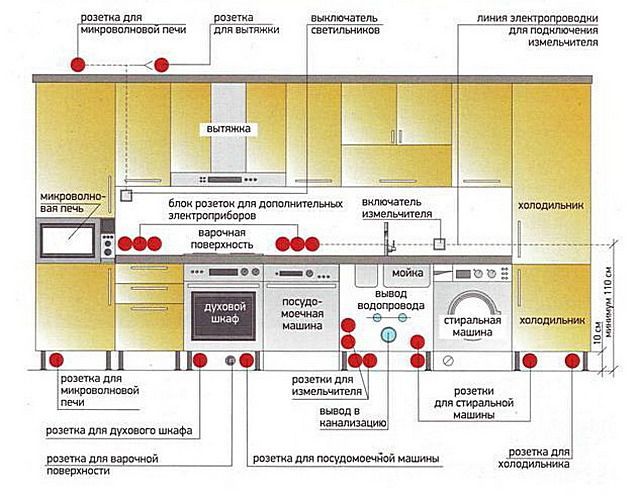
The kitchen is a very special room in terms of electrical wiring
And this is claimed to be still not the most "fancy" option. Nevertheless, if you sit down quietly with a sheet of paper, a pencil and a calculator, you can very clearly and qualitatively calculate.
So scheme reader be learned from calculation rules - familiar, fundamentals cabling part of it, too, is already known. You can safely get to work, and assistants in this, let him become the article of our portal, which will tell in detail about receptions installation of wires in junction boxes , about the types of contact connections , about installing sockets and switches, connecting large appliances andlargely drugom. Vse it - in sections «Electrical and lighting» and «Elektroprivreda private house» .
And the last remark. The author of this publication is fully aware that any teacher of electrical engineering would be punched for the quality of graphic charts "juicy deuce", so perhaps in the comments will be criticisms about it. However, the goal was not to teach site visitors how to draw. The main thing that the reader understand the principle, using which it can independently plan their household power.


