A semiconductor device called a zener diode is the main element of a stabilized power supply. It provides a constant voltage level. However, during operation, for one reason or another, it may fail. A specialist performing repair work needs to know how to check a zener diode for serviceability, or, as it is also called, a Zener diode.
Content:
- General information about the principle of operation
- Checking with a multimeter
- Checking with a transistor tester
- Scheme for verification
- Case studies
General information about the principle of operation
If you do not know how a zener diode works, then before reading the current article, read the previously published one - https://samelectrik.ru/kak-rabotaet-stabilitron-i-dlya-chego-on-nuzhen.html.
When a certain voltage is reached, an avalanche-like breakdown of the pn junction occurs. The transition resistance decreases. As a result, the voltage across the diode remains constant. And the current flowing through the semiconductor increases.
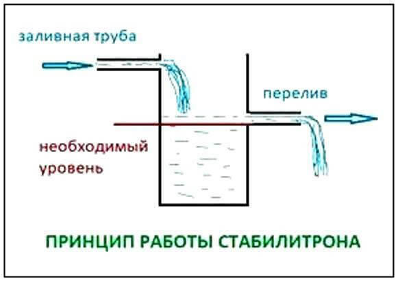
The principle of operation can be illustrated by a water barrel with an overflow tube. No matter how much water we pour into the barrel, the level will remain at a constant level.
The figure below shows the scheme of work using the example of a barrel of water.
 This element on the diagram turns on in the opposite direction. Those. plus to minus, and minus to plus. If you turn it on in the forward direction, then it will work like an ordinary diode.
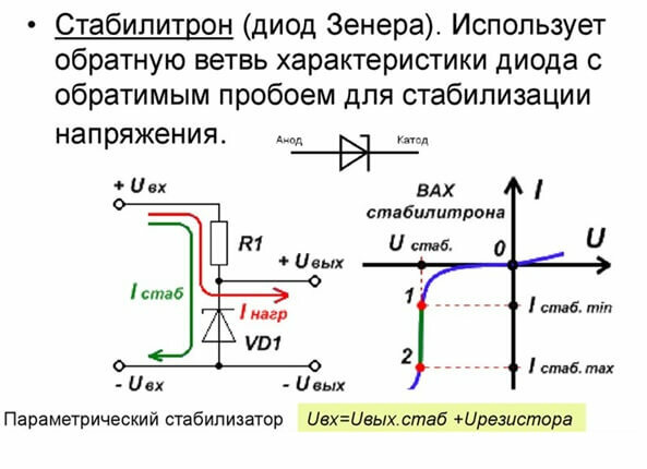
The figure above shows the current-voltage characteristic, the designation on the diagram and its inclusion.
Checking with a multimeter
A faulty zener diode affects the stabilization voltage of the power supply, which affects the performance of the equipment. Therefore, it is important for a specialist to know how to check a zener diode with a multimeter for serviceability.
The check is carried out in the same way as a diode. If you turn on the multimeter in resistance measurement mode, then when connected to a zener diode in direct direction (red probe to the anode), the device will show the minimum resistance, and in the opposite direction - Infinity. This indicates the health of the semiconductor.
Similarly, the zener diode is checked with a multimeter in the diode test mode. In this case, a voltage drop in the region of 400-600 mV will be displayed on the screen in the forward direction. In the opposite, either I, the left side of the screen, or .0L, or some other sign that speaks of "infinity" in dimensions.
The figure below shows the test procedure with a multimeter.
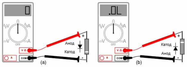 If the diode is broken, then it will ring in both directions. In this case, the tseshka may show a slight deviation of resistance from 0. If the pn junction is in a cliff, then regardless of the direction of switching on, the readings of the device will be absent.
In a similar way, you can check the zener diode without unsoldering from the circuit. But in this case, the device will always show the resistance of the elements connected in parallel to it, which in some cases will make verification in this way impossible.
However, such a check by a Chinese tester is not complete, because the check is carried out only for a breakdown, or for a break in the transition. For a complete check, you need to assemble a small circuit. You can see an example of such a circuit for checking the voltage of a zener diode in the video below.
Checking with a transistor tester
You can check the performance of semiconductor elements using a universal tester of radio components. It is often called transistor tester.
It is a universal measuring instrument with a digital indicator. Using a transistor tester, you can check various radio components. These include resistors, capacitors, inductors. And also semiconductor devices, transistors, thyristors, diodes, zener diodes, suppressors, etc.
To check the functionality, clamp the part in the ZIF-socket (a special connector with a lever for clamping the elements), after which the schematic designation of the element is displayed on the display. However, the items discussed in this article are tested as ordinary diodes. Therefore, you should not rely on the transistor tester to determine the voltage of the zener diode. To do this, you will still need to assemble a circuit like the one shown above or such as we will consider further.
We recommend watching a video about what a universal transistor tester is and how to check electronic components with it.
The tester, like a multimeter, checks the integrity of the pn junction and correctly determines the stabilization voltage of the zener diodes up to 4.5 volts.
When repairing equipment, it is recommended to change the stabilization element to a new one. Regardless of the presence of a good p-n junction. Because there is a high probability that the stabilization voltage of the diode has changed or it can change arbitrarily during the operation of the equipment.
Scheme for verification
Consider another simple circuit for determining the stabilization voltage, which consists of:
- Regulated power supply. The constant voltage should change smoothly with a potentiometer from 0 to 50 V (the higher the maximum voltage, the greater the range of elements you can check). This will allow you to test almost any low-power zener diode.
- A set of current limiting resistors. Usually they have a nominal value of 1 Kom, 2.2 Kom and 4.7 Kom, but there may be more. It all depends on the voltage and stabilization current.
- Voltmeter, you can use an ordinary multimeter.
- Shoe with spring-loaded contacts. It must have several cells in order to be able to connect semiconductors with different packages.
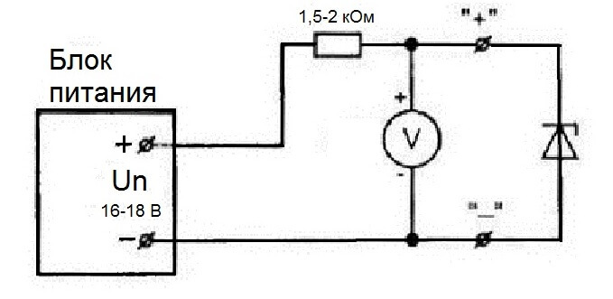
To check, connect a zener diode according to the above scheme and gradually raise the voltage at the power source from 0. At the same time, the readings of the voltmeter are monitored. As soon as the voltage on the element stops growing, regardless of its increase on the power supply, this will be voltage stabilization.
If there is a marking on the element, then the data obtained during the measurement is checked against the table in the parameter guide.
Note that zener diodes can be produced in various designs. For example, KS162 are produced in ceramic cases, KS133 in glass, D814 and D818 in metal.
Here are the characteristics of some common domestic zener diodes:
- KS133a stabilization voltage is 3.3 V, produced in a glass case;
- KS147a maintains the voltage at 4.7 V, the case is glass;
- KS162a - 6.2 V, ceramic body;
- KS175a - 7.5 V, has a ceramic body;
- KS433a - 3.3 V, produced in a metal case;
- KS515a - 15 V, metal case;
- KS524g - in a ceramic case with a voltage of 24 V;
- KS531v - 31 V, ceramic body;
- KS210b - stabilization voltage 10 V, ceramic body;
- D814a - 7-8.5 V, in a metal case;
- D818b - 9 V, metal case;
- D817b - 68 V, in a metal case.
To test a zener diode with high stabilization voltages, another circuit is used, which is shown in the figure below.
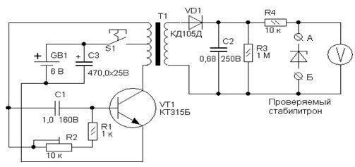
The check is carried out similarly to the described method. Similar devices are produced by Chinese manufacturers.
However, you can assemble the simplest circuit for testing zener diodes using a multimeter. This is well illustrated in the video below.
It should be warned that the electrical circuit shown in the video is not recommended to be used, because it is unsafe and requires safety precautions. Otherwise, you can get injured (at best).
Case studies
Sometimes zener diodes are checked on an oscilloscope, but for this it is necessary to assemble a special circuit.
The figure below shows a diagram of the set-top box and its connection to the oscilloscope.
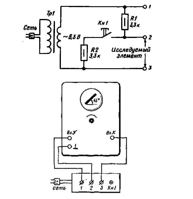
However, checking the oscilloscope should be done by a technician who is good at using it.
Zener diodes are often used as limiting or safety devices. For example, as protection against overvoltage on the hard drive, or rather, at its power input there are zener diodes or suppressors for 6 and 14 volts. Excessive voltage leads to their breakdown or burnout. To check, they simply solder these elements, and check the hard drive without them. If everything turns on, it's the zener diodes. They are replaced with new ones.
Another example from the practice of repairing scooters, namely, after incorrect installation of the alarm (and not only), sometimes the Zener diode mounted in the ignition lock on the Honda Dio 34 fails. It lowers the voltage of the on-board network from 12 V to 10 V, after which the scooter can be started. If the element is out of order, the moped will not start. The semiconductor can be replaced with a similar one with a voltage of 3.9. The situation is similar on other models of scooters from Honda: AF35, AF51, etc.
So we examined the main ways to check zener diodes, share cases from your practice in the comments and ask questions!
