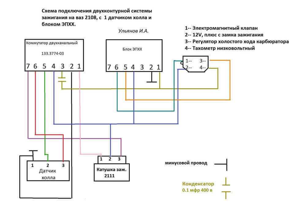
An electrical diagram is a document in which, according to the rules of GOST, the connections between the components of devices operating due to the flow of electricity are indicated. As you can imagine, this drawing gives electricians an understanding of how the installation works and what elements it consists of. The main purpose of the wiring diagram is to help in connecting installations, as well as troubleshooting a circuit. Next, we will tell you what are the types and types of electrical circuits, providing a brief description, characteristics and examples of each type.
Content:
- General classification
- The purpose of each wiring diagram
- Structural
- Functional
- Principled
- Mounting
- United
General classification
First, you need to figure out what is meant by types, and what is meant by types of documents. So, according to GOST 2.701-84, there are the following types of circuits (short designation in brackets):
- Electric (E).
- Hydraulic (G).
- Pneumatic (P).
- Gas (X).
- Kinematic (K).
- Vacuum (B).
- Optical (L).
- Energy (P).
- Divisions (E).
- Combined (C).
As for the types, the main ones are:
- Structural (1).
- Functional (2).
- Principal (complete) (3).
- Connections (assembly) (4).
- Connections (5).
- General (6).
- Location (7).
- United (8).
Based on the indicated designations, it is possible to understand its type and type by the name of the electrical circuit. As an example, a document called E3 is a circuit diagram. It looks like this:
Next, we will consider in detail the purpose and composition of each of the listed types of electrical circuits. We recommend that you familiarize yourself with standard schematic symbolsto make it even easier to understand what each drawing is.
The purpose of each wiring diagram
Structural
This type of document is the simplest and gives an understanding of how an electrical installation works and what it consists of. The graphic representation of all elements of the circuit allows you to initially see the overall picture in order to proceed to a more complex connection or repair process. The reading order is indicated by arrows and explanatory inscriptions, which allows even a novice electrician to understand the structural electrical diagram. You can see the construction principle in the example below:
Functional
The functional wiring diagram of the installation, in fact, does not differ too much from the structural one. The only difference is a more detailed description of all the constituent nodes of the chain. This document looks like this:
Principled
The schematic diagram is most often used in distribution networks, because gives the most disclosed explanation of how the considered electrical equipment works. In such a drawing, all functional units of the circuit and the type of connection between them must be indicated. In turn, the basic wiring diagram can have two varieties: single-line or complete. In the first case, only primary networks, also called power networks, are shown in the drawing. You can see an example of a single line image below:
The complete schematic diagram can be expanded or elemental. If the electrical installation is simple and all explanations can be applied to one main drawing, it is enough to make a detailed plan. If you are dealing with complex equipment, which includes a control, automation and measurement circuit, it is better to split all the individual units into different sheets so as not to get confused.
There is also a basic wiring diagram of the product. This type of document is a kind of copy from the general plan, on which it is indicated only how it works and what a certain node consists of.
Mounting
We most often use this type of electrical circuits on the site when we talk about how to independently perform installation of electrical wiring. The fact is that on the wiring diagram, you can show the exact location of all circuit elements, the way they are connected, as well as the alphanumeric characteristics of the installations making up the drawing. Taking as an example wiring diagram in a one-room apartment, on it we will see where to place sockets, switches, lamps and other products.
The main purpose of the wiring diagram is a guide for conducting electrical work. According to the prepared drawing, you can understand where, what and how to connect.
By the way, the wiring diagram is also considered to be a wiring diagram, which is designed to connect electrical equipment, as well as connect installations to each other within the same circuit. At connecting household appliances are guided by the wiring diagram.
United
Well, the last electrical circuit used in distribution networks is a combined one, which can include several types and types of documents. It is used in the event that it is possible to designate all the important features of the circuit without a strong pile-up of the drawing. A joint project is used most often in enterprises. For home craftsmen, this type of scheme is unlikely to be encountered. You can see an example below:
There is also a cable route diagram, which is a simplified plan for laying a cable line to distribution points and transformer substations. Its purpose is similar to an electrical wiring diagram - with the help of this document, installers are guided how to draw a line from point A to point B.
Finally, we recommend watching a useful video on the topic:
So we examined the main types and types of electrical circuits, as well as their purpose and characteristics. Knowing the conventions and having all the necessary documentation at hand, it is not at all difficult to understand how a particular installation works.
It will be interesting to read:
- Types of electric underfloor heating
- What are the cable channels
- Schematic drawing programs


