The basis for reliable and long-term operation of electronic equipment is a stable supply voltage. For this, stabilized power supplies are used. We can say that the main element that determines the output voltage level of the power supply is a semiconductor device - a zener diode. It can be both the basis of a linear stabilizer and a threshold element in the feedback circuit of a switching power supply. In this article we will tell the readers of the site Electrician himself about the device and the principle of operation of the zener diode.
Content:
- What it is
- Main characteristics
- Conventional graphic designation on the diagrams
- Connection diagram
- Marking
What it is
The literature provides the following definition:
Zener diode or Zener diode is a device designed to stabilize voltage in electrical circuits. Works with reverse bias in breakdown mode. Before the onset of breakdown, it has a high transition resistance. The currents flowing in this case are insignificant. They are widely used in electronics and electrical engineering.
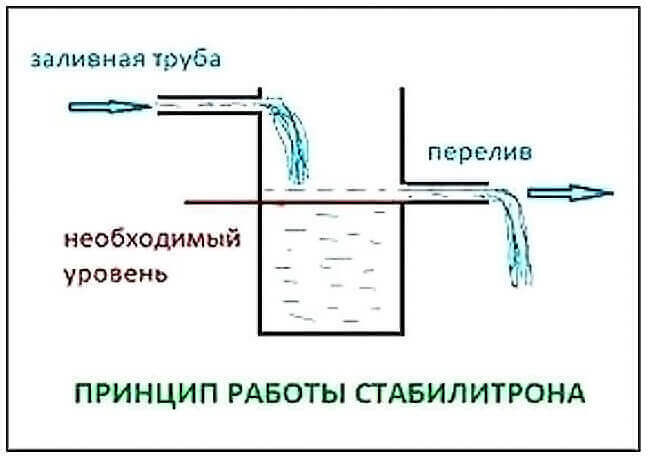
In simple terms, the Zener diode is designed to stabilize the voltage in electronic circuits. It is included in the circuit in the opposite direction. When the voltage exceeds the stabilization voltage, a reversible electrical breakdown of the pn junction occurs. As soon as it drops to the nominal, the breakdown stops and the zener diode closes.
The figure below is a graphical diagram for dummies to understand how the Zener diode works.
The main advantages are low cost and small dimensions. The industry produces devices with a stabilization voltage of 1.8 - 400 V in metal, ceramic or glass cases. It depends on the power for which the zener diode is designed and other characteristics.
To stabilize high-voltage voltage from 0.4 to several tens of kV, glow-discharge zener diodes are used. They have a glass body and were used in parametric stabilizers before the advent of semiconductor devices.
Devices that change their resistance depending on the applied voltage have similar properties - these are varistors. The difference between a zener diode and a varistor is that the latter has bi-directional symmetrical characteristics. This means that, unlike diodes, it has no polarity. Briefly the varistor is designed to provide overvoltage protection electronic circuits.
Suppressors are used to protect the equipment from voltage surges. The difference between a zener diode and a suppressor is that the former gradually changes its internal resistance depending on the applied voltage. The second, when a certain voltage threshold is reached, opens immediately. Those. its internal resistance tends to zero. The main purpose of suppressors is to protect equipment from power surges.
The figure below shows a conventionally graphic designation (UGO according to GOST) of a semiconductor and its current-voltage characteristic.

In the figure, the numbers indicate section 1-2. It is working and is designed to stabilize the voltage in the circuits. If the device is turned on in the forward direction, then it will work like a normal diode.
We recommend watching the following video to study in more detail the principle of operation of the zener diode, the designation of the elements and their area of application.
Main characteristics
When designing power supplies, you should be able to correctly calculate and select the necessary element according to the values. An incorrectly selected zener diode will immediately fail or will not maintain the voltage at the required level.
The main characteristics are:
- voltage UcT. stabilization;
- rated stabilization current IArt.flowing through a zener diode;
- allowable power dissipation;
- temperature coefficient of stabilization;
- dynamic resistance.
These characteristics are determined by the manufacturer and are indicated in the reference literature.
Conventional graphic designation on the diagrams
All devices have a graphic designation. This is necessary so as not to clutter up the electrical circuit. The zener diode has its own graphical designation, which is approved by the interstate standard for a single standard for design documentation (ESKD).
The figure below shows how it is indicated in the diagram according to GOST 2.730-73, the zener diode is practically designated as a diode, since, in fact, it is one of its varieties.

For the correct inclusion, you should distinguish where the plus, where the minus. Looking at the above figure, the plus (anode) is on the left and the minus (cathode) is on the right. According to ESKD, the dimensions of the UGO diodes should be 5/5 mm. This is illustrated in the figure below.

Connection diagram
Consider the operation of a zener diode using the example of a parametric stabilizer circuit. This is a typical layout. Here are the formulas for calculating the stabilizer.
Let's say that there is 15 Volts, and the output needs to be 9 V. According to the voltage table in the reference book, we select the Zener diode D810. Let's calculate the current-limiting resistor R1, according to the figure below. It shows the current limiting resistor and connection diagram. The voltage regulation mode is marked on the current-voltage characteristic 1.2.

In order for the semiconductor not to fail, it is necessary to take into account the stabilization current and the load current. Determine the stabilization current from the reference book.
It is equal to 5 mA. The figure below shows part of the reference book.

We assume that the load current is 100 mA:
R1 = (Uin-Ust) / (In+ IcT) = (15-9) / (0.1 + 0.005) = 57.14 ohms.
If you need a powerful stabilizer, then it is worth assembling a circuit from a zener diode and a transistor.

If it is necessary to make a stabilizer for a small voltage of 0.2-1 V, a stabilizer is used for this. It is a kind of zener diode, but it works in the forward branch of the I - V characteristic and turns on in the forward direction, which is its unique feature.
Similarly, you can make a power supply, where the stabilizer is made of diodes. Like the stabilizer, they are turned on in the forward direction. The required voltage is gained by direct voltage drops across the diode, for silicon diodes it is in the range of 0.5-0.7V. In the absence of diodes, you can assemble a Zener diode from a transistor.
The figure below shows a transistor circuit.

The industry also produces controlled zener diodes. Or, more precisely, this is a microcircuit - TL431. This is a universal microcircuit that allows you to regulate the voltage in the range from 2.5 to 36 volts.
The adjustment is carried out by selecting a resistance divider. The diagram below shows a 5 volt regulator. The divider is assembled on resistors with a nominal value of 2.2 K.

The specialist should know how to check the operation of the zener diode with a multimeter. Immediately, we note that only a unidirectional element can be checked; doubled (bidirectional) elements are not subject to such a check. If the Zener diode is working properly, then when the tester "dials" in one direction, it will show an open circuit, and in the second, the minimum resistance. The faulty one rings both ways.
Marking
Depending on the power of the diode, they are available in different packages. On metal cases of high power, the letter designation of the type of device is indicated.
The photos below show Soviet-made devices and how they looked.


Nowadays low-power diodes are produced in glass cases. The marking of imported devices is color-coded. The body is marked with stripes or colored rings.
The figure below shows the marking of SMD diodes.

Domestic diodes in glass cases are marked with stripes or rings. You can determine the type and parameters using any reference book of electronic components. For example, the green bar indicates the KS139A zener diode, and the blue bar (or ring) indicates the KS133A.
On powerful devices in metal cases, a letter designation is indicated, for example, D816, as shown in the photo above. This is necessary in order to know how to choose an analogue.
So we examined what zener diodes are, how they work and what they are for. If you have any questions, ask them in the comments below the article!
Related materials:
- What is a transistor tester
- How a resistor works
- How to solder radio components from boards