Slip is one of the main characteristics of an electric motor. It varies depending on the operating mode, shaft load and supply voltage. Let's take a closer look at what an electric motor slip is, what it depends on and how it is determined.
Content:
- What it is
- Slip value in different operating modes
- Measurement methods
What it is
The principle of operation of the three-phase asynchronous motor pretty simple. A supply voltage is applied to the stator winding, which creates a magnetic flux, in each phase it will be displaced by 120 degrees. In this case, the summing magnetic flux will be rotating.
The rotor winding is a closed loop, it induces EMF and the resulting flux imparts rotation to the rotor, in the direction of movement of the stator flux. Rotating electromagnetic moment tries to equalize the rotation speeds of magnetic fields stator and rotor.
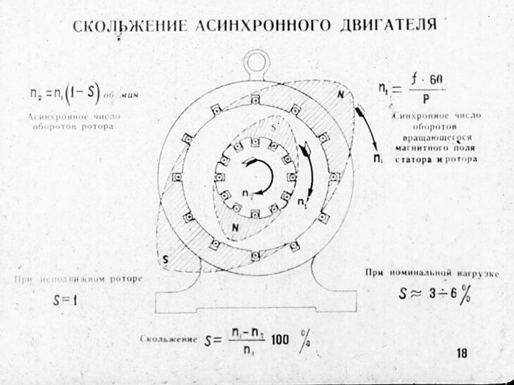
The value that determines the difference in the speeds of rotation of the magnetic fields of the rotor and stator is called slip. Since the rotor of an induction motor always rotates slower than the stator field, it is usually less than one. It can be measured in relative units or percentages.
It is calculated by the formula:

where n1Is the frequency of rotation of the magnetic field, n2 Is the frequency of rotation of the rotor magnetic field.
Slip is an important characteristic that characterizes the normal operation of an induction motor.
Slip value in different operating modes
In idle mode, slip is close to zero and is 2-3%, due to the fact that n1 almost equals n2. It cannot be equal to zero, because in this case the stator field does not intersect the rotor field, in simple words, the motor does not rotate and the voltage supplying it is not supplied.
Even in perfect idle mode, the amount of slip expressed as a percentage will not be zero. S can also take negative values, in the case when the electric motor is operating in generator mode.
In the generator mode (the rotation of the rotor is opposite to the direction of the stator field), the EM slip will be in the values of -∞
There is also a mode of electromagnetic braking (rotor opposition), in this mode the slip takes on a value greater than one, with a plus sign.

The value of the current frequency in the rotor windings is equal to the mains current frequency only at the moment of starting. At rated load, the current frequency will be determined by the formula:
f2= S * f1,
where f1 Is the frequency of the current supplied to the stator windings, and S is the slip.
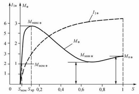
The frequency of the rotor current is directly proportional to its inductive reactance. Thus, the dependence of the current in the rotor on the slip of the IM appears. The torque of the electric motor depends on the value of S, since it is determined by the values of the values of the magnetic flux, current, the angle of shift between the EMF and the rotor current.
Therefore, for a detailed study of the characteristics of blood pressure, the dependence shown in the figure above is established. Thus, the change in torque (at different values of slip) in an IM with a wound rotor can be controlled by introducing resistance into the circuit of the rotor windings. In electric motors with a squirrel-cage rotor, the torque is regulated or by means of frequency converters or the use of variable speed motors.
At the rated load of the electric motor, the slip value will be in the range of 8% -2% (for small and medium power motors), the rated slip.
With an increase in the load on the shaft (torque on the shaft), slip will increase, in simple terms, the magnetic field of the rotor will increasingly lag behind (slow down) the magnetic field of the stator. An increase in slip (S) will lead to a proportional increase in rotor current, therefore, the torque will increase proportionally. But at the same time, active losses in the rotor increase (resistance increases), which reduce the increase in current strength, so the torque increases more slowly than slip.
At a certain amount of slip, the torque will reach its maximum value, then it will begin to decrease. The value at which the moment will be maximum is called critical (Scr).
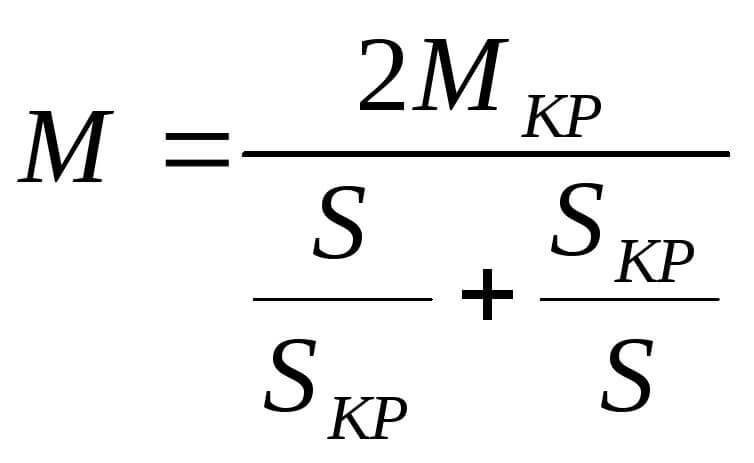
In graphic form, the mechanical characteristic of an induction motor can be expressed using the Kloss formula:

where, MTo - this is the critical moment, which is determined by the critical slip of the electric motor.
The schedule is built based on the characteristics specified in the AD passport. If you have any questions about the drive, this graph is used as a mover using an asynchronous electric motor.
The critical moment determines the value of the permissible instantaneous overload of the electric motor. With the development of a more critical torque (hence, a more critical slip), the so-called overturning of the electric motor occurs and the engine stops. Rollover is one of the emergency modes.

Measurement methods
There are several ways to measure slip of an induction motor. If the rotational speed significantly differs from the synchronous one, then it can be measured using a tachometer or tachogenerator connected to the EM shaft.
The stroboscopic measurement with a neon lamp is suitable when the slip is not more than 5%. To do this, a special line is either applied to the engine shaft with chalk, or a special stroboscopic disc is installed. They are illuminated with a neon lamp, and the rotation is counted for a certain time, then, according to special formulas, calculations are made. It is also possible to use a full strobe like the one shown below.
Also, the inductive coil method is suitable for measuring the slip value of all kinds of machines. The coil is best used from a relay or contactor direct current, due to the number of turns (there are 10-20 thousand), the number of turns must be at least 3000. A coil with a sensitive millivoltmeter connected to it is placed at the end of the rotor shaft. According to the deviations of the arrow of the device (the number of oscillations) for a certain time, the slip value is calculated using the formula. In addition, for an induction motor with a wound rotor, slip can be measured using a magnetoelectric ammeter. The ammeter is connected to one of the phases of the rotor and, according to the number of deviations of the ammeter needle, calculations are made (according to the formula from the method with an inductive coil).
So we examined what the slip of an induction motor is and how to determine it. If you have any questions, ask them in the comments below the article!
Related materials:
- Types of tests for induction motors
- Rules for determining the phase, zero and ground in the network
- How to choose a multimeter for home and work
Your e-mail will not be published. Required fields are marked *

