Pump station with accumulators and pressure switches
Modern hydraulic drives for independent water supply work because the excess pressure in the air chamber. The principle of operation of pneumatic accumulators built on the interaction of compressed air and water. Pump It pumps water into the blower, which is located within the housing. The volume of the air chamber decreases and the pressure increases. In the intervals between the insertion unit pushes the air supply of water from the membrane in the user network.
Water does not contact the inner walls of the sealed container. Membrane separates the air chamber from the metal housing. If the accumulator is used in the drinking water, the membrane material is chemically inert rubber. When using a storage tank in a heating system or hot water using a membrane with high resistance to high temperatures.

The design of the diaphragm tank
There are vertical and horizontal models of air storage tanks of various capacities. Circuit connecting the accumulator determines the type of pump and drive model. Horizontal tanks are used for the extension of the surface units. The supercharger pressure mounted on the platform at the top of the drive housing (i.e., the cylinder is below the self-priming pump).
Related article:
Regulation of water pressure switch to adjust the pump. Having familiarized with simple water pressure switch adjustment rules, as well as the intricacies of the settings can be carried out such work on their own.
Pumping stations with submersible units complement the vertical drives. The accumulator is above the downhole pump installation.
Displacement hydropneumatic storage tank depends on the time the water flow rate, and pump power switching frequencies height piping system. The higher water flow and less pressure drop across the on / off the pump, the greater the capacity of the accumulator.

Typical scheme independent water from the well
Structural elements of the accumulator:
- a sealed metal enclosure, designed for operation under pressure (1,5 ÷ 6 atmospheres);
- elastic membrane - an internal water storage tank;
- flange for attaching the valve membrane to the shell and fill it with water;
- nipple for injection of air into the air cylinder chamber;
- Valve for venting of the water chamber (for accumulators which exceed 100 liters);
- bracket for a small tank on the wall or the support legs with rubber gaskets for the installation of higher capacity models;
- a horizontal tank included support bracket to be installed together with the surface pump pressure accumulator and the pressure switch.
Important!Initial filling of the hydraulic accumulator cylinder produce water gradually so as not to damage the integrity of the pears, since after storage rubber membrane walls are usually glued together.

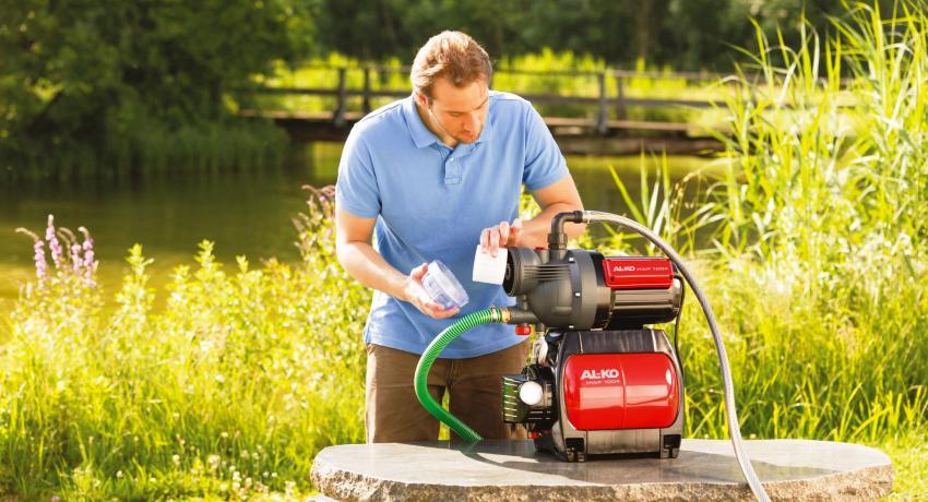
The pumping station will help to achieve a full-fledged independent water garden
Calculation of accumulator volume
Method of selection of the hydraulic accumulator is designed for individual houses, which consume a large amount of water (sewerage, Bathroom, shower, a few taps, bidet, washing machine and dishwasher). According to the number of delivery points determine the total consumption rate and the maximum flow rate of water for drinking purposes. The volume of the accumulator is determined by the formula:

V - the volume of the accumulator, L;
Qmax - maximum water flow for drinking purposes, l / min;
and - the number of system startups per hour (the recommended value is 10 starts);
Pmin - pump ON pressure, atm .;
Pmax - pump OFF pressure, atm .;
Po - pressure air accumulator chamber atmospheres.

supply structure consists of: 1 - the accumulator; 2 - pump; 3 - the pressure switch; 4, the check valve; 5 - Power
A standard water supply installation for a small house with seasonal accommodation usually equipped with accumulator capacity of 24 liters. Housing with a number of analysis points over three selected storage capacity of 50 liters. And the data sheet equipment manufacturer indicates the total volume of the container (air chamber included).
Adjusting the operating pressure accumulator
For domestic water supply of one-storey houses, a pressure in the atmosphere is considered to be sufficient. Note, however, that the air pressure of the air chamber should be greater than the static pressure of water of bidders highest point.
Maximum off pressure depends on the pressure characteristics of the pump. The pressure which the pump pumps, divided by 10, corresponds to the upper threshold for the automatic water system. Amendment made to the linear flow resistance, the actual mains voltage, the technical condition of the equipment and the height of the home water supply system.

Components for adjusting the water pressure in the hydraulic reservoir
The recommended pressure difference between the pump on and off for independent water is 1.0 ÷ 1.5 atmosphere. Increasing the factory settings (1.5 atmosphere) reduce the reserve volume and increase the pressure in the system. High pressure cold water consumption increases, leading to inefficient use of energy resources.
The formula for calculating the value of the desired pressure in accumulator:

Hmax - the height in meters from the center line of the accumulator to the top of the water sampling points (for a two-story private house 6 ÷ 7 meters).
The air pressure in the air chamber of the damper vessel is checked and adjusted prior to installation, or on failure settings abnormality water. During adjustment powered pumping station disconnected from the network, the water drained from the accumulator.

All elements are fastened together by means of fittings
Pneumatic valve air chamber is located under the decorative cap on the tank body. Value or pressure deviation from the predetermined operating parameters determined by means of a manometer connected to the spool. According to the results of measurement of the excess air is vented or pump up the air chamber pressure motor pump.
If the adjustment of the working parameters of the accumulator has not brought the desired result, then check the pressure switch settings.
An apparatus for accumulator pressure switch
The pressure switch controls the operation of the pump and adjusts the filling of fluid accumulator. The device integrates, monitors and regulates the cold water supply equipment.
Appearance of the pump control unit resembles a small plastic box. The device is mounted at the entrance to the storage tank. The pressure switch for the hydraulic accumulator consists of a mechanical and electrical parts.

The design of the pressure switch and its adjustment
The spring adjustment mechanism and the junction box protects the plastic cover. The metal base plate bottom supports the plastic housing. The base separates the actuator (membrane with the piston) of the actuator (hinged platform, two adjusting springs on the studs and the electrical contact assembly).
The electrical pressure switch of the water is double contact relay switching circuits. Feet electrical contact assembly sandwiched between the metal base plate and the plastic housing. Two couplings for clamping the cable (mains and the pump supply line) and connect the relay node to the hydraulic accumulator located at the base of the plastic housing.
Standard diameter of inlet ¼ inch. From the internal device cross section to the adapter mounting nut rubber membrane is limited. Reciprocation elastic membrane communicates brass piston which transmits force hinge metal platform.

The pressure gauge is used to measure water pressure
From above, the movable edge of the platform, crush large and small spring force which counteracts the piston. large compression spring adjusts the degree of the pump. The range of small deformations of the spring unit provides a trip pressure.
Ways to connect the pressure switch to the pressure accumulator
Distinguish pressure switch connection circuit to the hydraulic accumulator of water and electricity.
How to connect a pressure switch on the water?
The connection node connecting the pressure switch to the accumulator pipe conduit is rigidly fixed. The device is mounted in an assembled state. Before assembly is necessary to provide sufficient space for rotating the housing for mounting the pressure switch.
The device is screwed on a separate thread embedded in the conduit or produce assembling directly with the outlet pressure accumulator through a special fitting. Fitting with five outputs allows to set the pressure gauge near the pump control device.

Connect the wires to the pressure switch
How to connect the pressure switch to the pressure accumulator of the electrical part?
Direct inclusion pressostat produce 220V under the condition that the power of the pump operating current does not exceed 10 amperes.
Before connecting the cable with the device is removed the protective plastic cover. Electric power cable or pump lines lead into the proper coupling. Outside wire crimp nut is fixed a plastic ring. Designation of groups of contacts indicated on the package. cable end is separated into strands. Phase, neutral, grounding cleaned by an insulating sheath and connected to the terminals of the contact group.
Important! Electrical and regulation works carried out at the equipment is disconnected from the network. Electrical connections carried out in compliance with the statutory rules of technical operation and safety in electrical installations.

Relay automates the pumping station and disconnects the supply of water when the predetermined mark
Rules pressure switches adjustment for hydraulic accumulator
The relay controls the minimum and maximum pressure in the accumulator tank maintains pressure difference at on / off the pump. Limit allowable relay setup values based on the time rate and pump power.
factory setting characteristics are specified in the technical data sheet. Standard pressure switch setting for water supply systems - 1.0 ÷ 5.0 atmospheres. Start Pressure - 1.5 atmosphere. engine operating range of the pump - 2.5 atmosphere. Maximum pressure off the unit - 5.0 atmospheres.
If the factory configuration settings are not relevant or failed installation work, setting and adjustment of the water pressure switch is carried out on their own, using a pressure gauge. The control meter is mounted on the manifold pressure accumulator. Correction is made on the pressure gauge, after the pump is turned off. The pressure drop to create an open tap in the hydraulic accumulator to the nearest water intake point.

Connecting the pressure switch and the switch box to a submersible pump
Accumulator pressure switch setting is carried out under pressure without shutting off the power supply from the pump station. The pump has to fill the holding tank and raise the pressure on the network. When the relay is triggered and the unit will shut off the engine, remove the plastic housing cover and fully loosen the tension of the small spring mechanism.
How to adjust the water pressure switch to the minimum pump output pressure?
Setting a large adjustment of the spring:
- the clamping nut is rotated in a clockwise direction to increase the starting pressure;
- easing tightness - reduces the relay operating pressure and activating the motor;
- to verify the result of adjusting the tap is opened and water is drained until the pump.

Adjusting the pressure switch by means of two nuts: large and small
How to adjust the pressure switches accumulator pressure pump shutdown?
Setting a small adjustment spring:
- a nut on the stud small twist spring to increase the pressure difference;
- attenuation of interference allows lower pressure engine shutdown;
- correction result is checked by a test switching on the pump.
If the pressure gauge reading coincides with the desired value when you turn on / turn off the engine, the adjustment is completed. When it is impossible to adjust the current of the device on its own, use the services of qualified professionals, or buy a new device. If you decide to buy a pressure switch for pressure accumulator, then pay attention to the compatibility of work with pumping equipment and the method of connection to the power supply.

Automatic protection against dry running on the basis of the four fittings
Important!Increasing the starting value factory setting accumulator pressure switch (higher than 1.5 atmospheres) creates a critical load on the diaphragm accumulator. Working range of the pump is altered into account the maximum allowable pressure for the water fittings. Limiting the pressure to which the seals are designed mixers and taps of 6 atmospheres.
Air pressure air accumulator chamber does not affect the pressure relay and pump stations in general. Absence or deficiency of air leads to an excessive stretching of the membrane and the actuation of the pump at each selection of water from the system. The increased excess pressure of the air chamber reduces the amount of supply of water in the membrane and triggering interval setting pressure. Frequent on-off time of the pump assembly reduces service life.
Normal operation of the pumping station can be provided that the air pressure accumulator chamber is 10% lower in pressure pump. Correct set-up and adjustment of pressure switches and pressure accumulator ensure the pump can not be overloaded, optimum filling of water storage. An integrated approach to setting up and adjusting the equipment will increase the life of the membrane and increase the reliability of an autonomous water supply system.