How to assemble profilegib their own hands - a simple way to manufacture it-yourselfers
Table of contents
-
1 All you need to know about profilegibe
- 1.1 How does profilegib
- 1.2 Build hand tube bender
- 2 To summarize
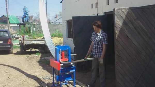
Simultaneous bending multiple tube with a square cross section available through the use of wide rolls on the machine
You do not know how to do profilegib their own hands? I offer a simple step by step instructions on which you can collect per day effective machine in action. Given that the price of factory machinery starts from $ 300, I am confident that the proposed guide will be useful to many.
All you need to know about profilegibe
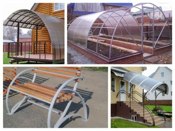
The photo shows only a small part of what can be made of metal profiles
Profilegib - a device for uniform bending metal pipes with a different cross-section profile. Furthermore, profilegiby can be applied to various cold-rolled bending shaped metal products, including channels, angles, brands, I-beams and so on. N.

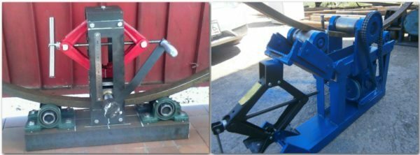
To the right is shown the machine, wherein the electric feed drive profile, and the left shows the machine with full manual control
Profilegib bending tool differs from the usual characteristic form of rollers, which repeats the deformed section steel. By type of clamping rollers differ manual and hydraulic profilegiby.
So it looks Roll Forming machine with a hydraulic clamp (right diagram of the pressing traditional bottom-up, and the left - top to bottom).
Hydraulic nip rollers ensures a greater force, allowing the metal to deform to a greater thickness. For example, some machines are equipped with jacks factory assembly with a force in excess of 8 tons. According to the type of drive, the feed to the rolling rollers, different hand tools and electrical profilegiby.
How does profilegib
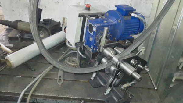
Due to the fact that for profilegiba shafts have indirect form, this machine works with metal corners
And manual and hydraulic profilegiby operate on the principle of cold mechanical deformation of the metal. The principle of operation of different machines different orientation of the deforming impact.
| schematic representation of | Operating principle |
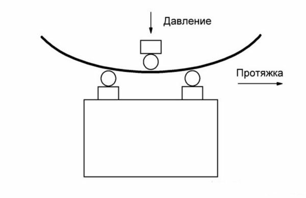 |
Pressure roller moves from the top downwards. This is the most common pattern profile deformation, since it works on most of the hand-held machines. Scheme pressing using the upper roller is rarely used in machine tools with the jack. |
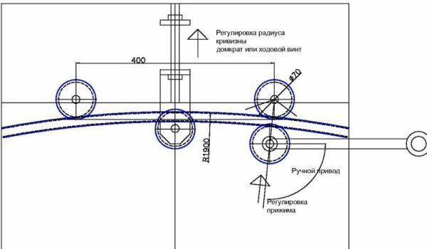 |
Pressure roller moves from bottom to top. The pressure deforming profile appears below. Such a scheme is traditional for machines with hydraulic jack. The central shaft moveable, while the side pinch rollers remain stationary. |
It should be noted that one and the other metal deformation diagram is equally effective. The difference in the direction of the force is explained only by the arrangement of expediency and rolling roller relatively static rollers.
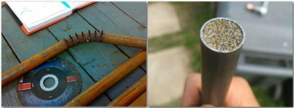
The deformation tube without machine - left tube bent at notch, and the right - for bending filled with sand
Build hand tube bender
Consider how to build a simple rolling bending machine profile with their own hands. Ready machine is designed for deformation of shaped tubes with a diameter not exceeding 60 mm.
| Illustration | Description of action |
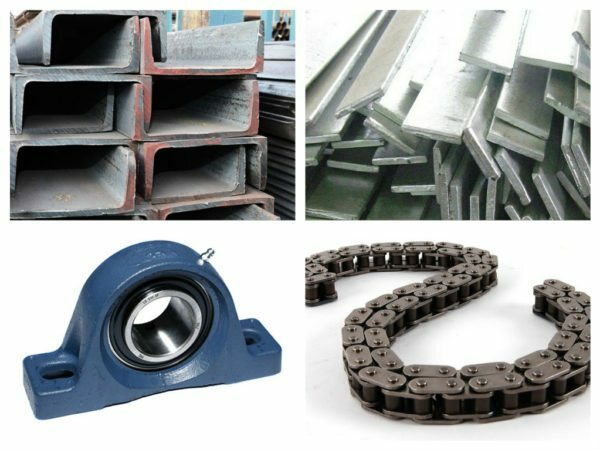 |
Prepare materials. To assemble homemade profilegib need:
|
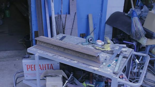 |
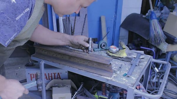
Prepare frame members. Cut lengthwise channel into 4 parts, of which 2 to 70 cm long and two transverse parts 20 cm. Two long longitudinal piece as shown in the photo, the ends cut off at an angle of 70 °. |
 |
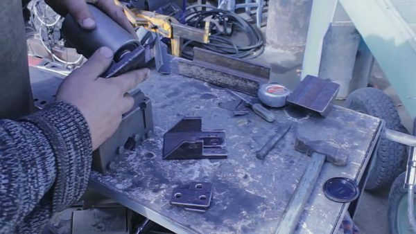
Mark and drill holes for the bearing units. To the top of the longitudinal sills are putting bearing assemblies and marks a place in the bolted. Punch, as shown in the photo, nakernivaem place in the drilling, and then make the through-holes. |
 |
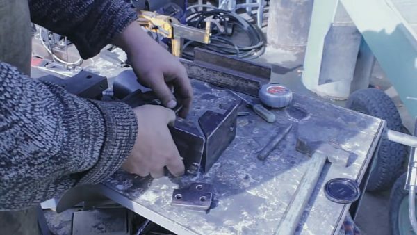
We produce lateral mounts the pressure roller. Side mount as shown in the photo, making of channel. Dimensions of mounting is not specifically indicated, as they are matched to the shaft, which is available. Under the shaft in mounts are drilled through holes. In the pressure roller will have a significant load space opening strengthening inserts made of steel strip so that the metal thickness at this point was not less than 10 mm. |
 |
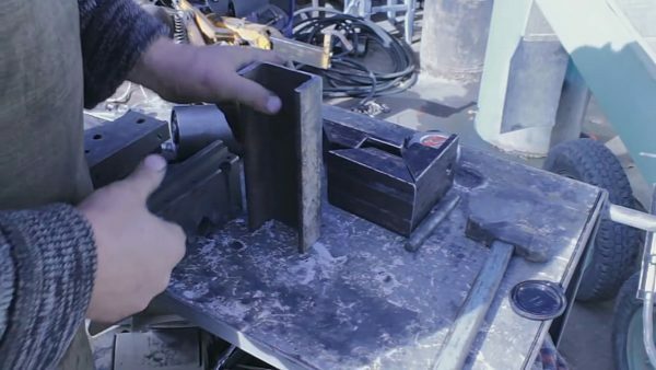
We make the upper part of the pressing unit. From the same piece of cut sill shaft and width as shown in the photo, crop it sidewall angle 45 °. As a result, two sidewalls and a top portion can be folded U-shaped frame, which will keep the shaft. |
 |
Prepare guides for clamping unit. Of channel cut into two columns 500 mm high. |
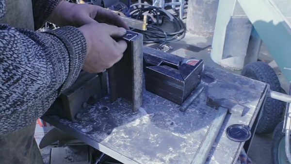 |
Welded plates for bolting. Cut two strips of steel plate, so that they are free to enter the cavity sill. Each plate is indented at 10 mm from the edge drill bolt holes with 12 mm diameter. The prepared plates are inserted and welded edges U-sections. |
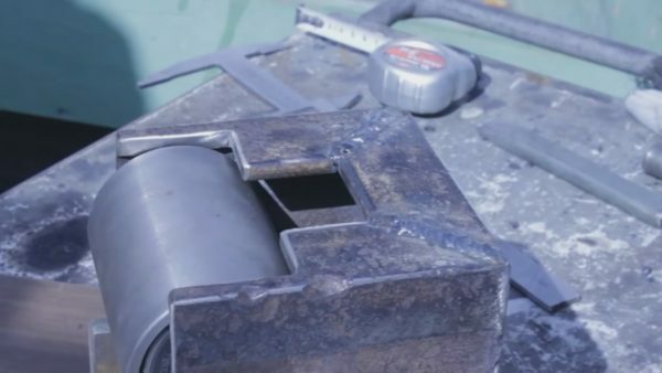 |
Putting pressure unit from movable roller. Of the two previously notched sidewalls and top weld single unit, which is inserted in the shaft during assembly. |
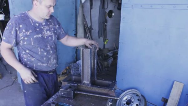 |
Putting the frame and vertical uprights. Of the previously cut longitudinal and transverse parts of the weld base collect and bending tool. Toward the bottom welds vertical guides, which will move the presser assembly. |
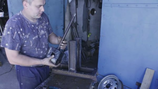 |
bolted. In the upper part of the pressing unit mark up the center at which drill hole diameter of 22 mm. The hole missing bolt M20. At the end of the bolt welded to the two overlap, so that the bolt rotate freely in the hole, but it did not come out. |
 |
To produce an upper guide bar. Cut piece sill size of the distance between the guides. Along the edges of the two drill holes, which should coincide with the holes already drilled in the guide. In the center of the hole is drilled, on top of which is welded to the bolt nut. |
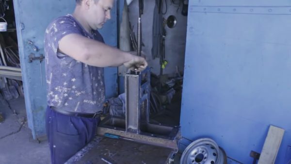 |
Bolted an upper crossbar. The openings in the upper crossbeam and a guide insert two bolts that tighten nuts through GROWER washers. |
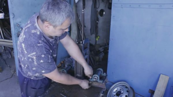 |
Fasten bearing units. We are putting a frame on top of the base housing units stacked in their shafts. Bearing Units, through the matching holes, fasten the bolts and nuts. Nuts are tightened after setting GROWER washers. |
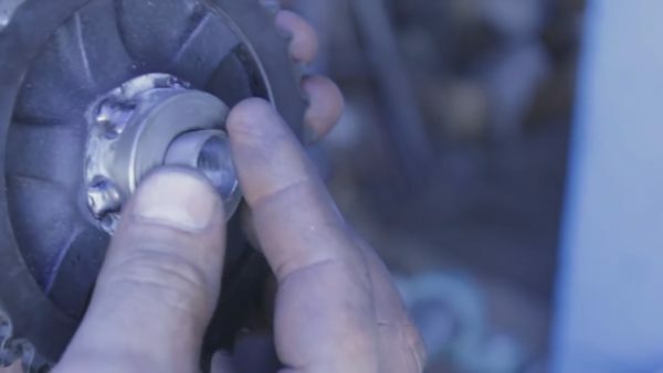 |
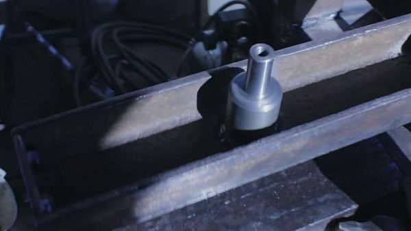
Is welded to the hub gears. Centered under the timing chain pinion hub is welded, the diameter corresponding to the spindle shaft. The hub is surfacing, and bore shaft. This complex structure and, if you want to simplify it, the gears can be simply welded to the shafts. |
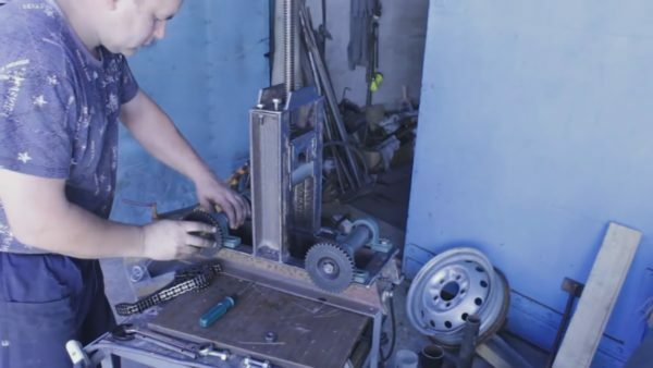 |
Install the gears on the shafts. Dress gear on the spindle and tighten the two nuts - one primary and the other X's. |
 |
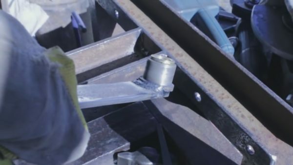
Welded under the gate axis. In the middle of the vertically extending guide side gears already installed, it is welded to the axis of the gate with the gears. axis location on the guide is defined in such a way that the chain was tight but at the same time it can be to throw, and if necessary - to remove. |
 |
Making the gate. Cut piece strip length 40-50 cm. On the one side gate welds metal bars, which will handle. On the other hand, welded on the hub of the cutting tube. The outer diameter of the tube should correspond to the inner diameter of gears harvested. |
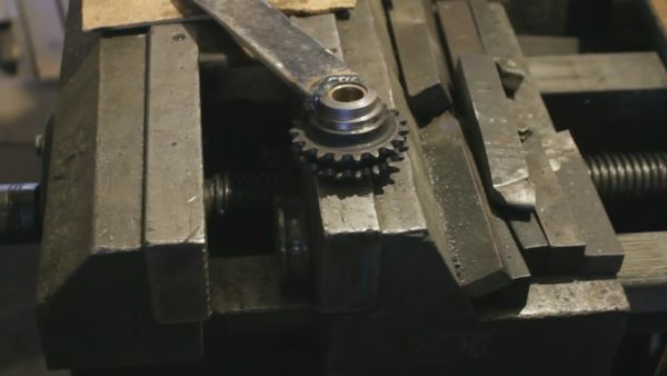 |
Overmolding gear on the handle. At the hub of the handle, with a vise, pressed onto the gear to the timing chain. To overmolding went faster and easier gear must be heated to at least 120 degrees. As a result, the fitting hole expands. After the item is cool, it fits girth hub. |
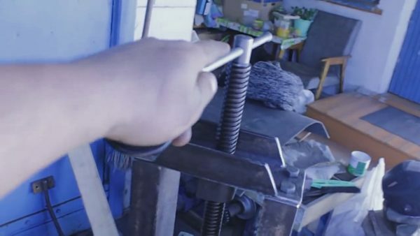 |
Make a goal to press block. At the end of the bolt is drilled through hole. The hole is pushed a scrap rod to get a grip. |
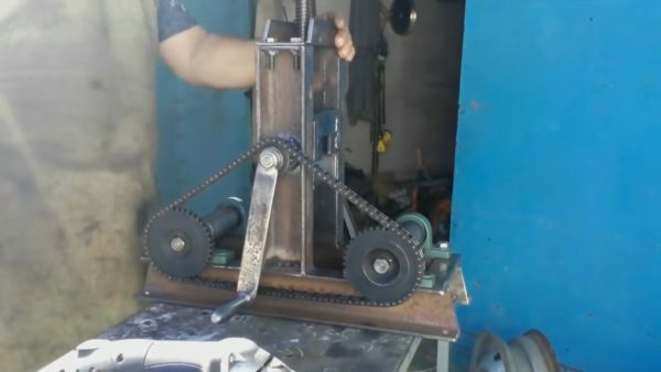 |
Installation of the side gates. At pre-fasten welded axle hub first gate and tighten nuts and X's. Through all three gears snapped chain. |
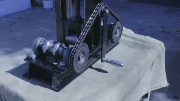 |
Painting. After manufacturing profilegiba, details that will not be subjected to friction during operation, can be painted to retard corrosion. |
To summarize
You learned how to make hand-profilegib to bend the profile tubes. I also suggest to watch the video in this article. If you have questions, be sure to ask them in the comments.
