Vibratory plate with his hands - the choice of materials and phased assembly instruction
Table of contents
-
1 How it works
- 1.1 type of drive
-
2 What can be done to
- 2.1 Materials and tools
- 2.2 Assembling tamping
- 3 In conclusion
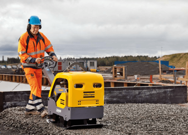
The use of vibrators is relevant not only when working with sandy soils, but also for compacting gravel
Want to know how is going to vibrating plate with your hands? I will tell you what necessary materials and tools and give a step by step assembly instructions. And to explain its operating principle and introduce a species of this equipment.
How it works
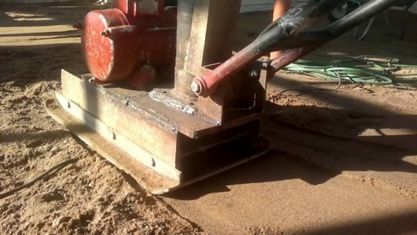
Seal sand bedding before pouring concrete screed
The principle of operation is based on the rotation of plate compactors eccentric which creates the wobble per revolution deposed the flywheel:
- Drive, due to movement of the load on the shaft creates a vibration that is transferred to the metal plate - sole;
- The heavier the plate in the bottom of the unit and the stronger the vibration, the more effective seal.
On a similar principle works shaker table, which are produced using extruded cinder block. Only in this case, the motor with an eccentric is not located above the work surface, and under it.
type of drive
Modern compactors are equipped with two types of drives:
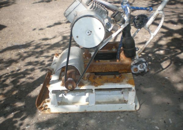
Homemade vibrating plate of motor cultivator - is taken from the old engine unit and frame, on which it is secured
- Gasoline or diesel engines. Internal combustion engines are used in heavy and massive units weighing more than 200 kg. Because the exhaust gases, gasoline or diesel vibrating plate is recommended for use in open areas.
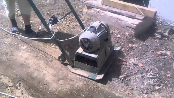
It looks like a compact electric vibration plates made entirely with their own hands
-
Electric motors. Compactors on the electric motor more compact in comparison with gasoline counterparts:
- Advantage elektrotrambovok - versatility, as they can be used not only in an open area, but inside the closed object;
- shortcoming electrical equipment - dependence on power, ie, the object must be electrified or generator to be used at the facility.
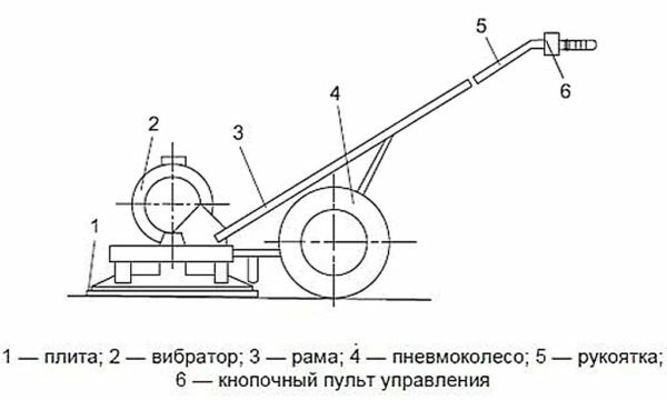
These drawings can be applied with the alteration in the rammer motoblock
Regardless of the actuator type vibrator life rarely exceeds 1000 hours. The vibration of the displacement of the flywheel on the shaft affects not only the board but also on the bearings in the shaft hub.
Wear of the bearings leads to jamming of the shaft. Therefore, at the end of the declared resource, the bearings must be replaced, even if they apparently look intact.
What can be done to
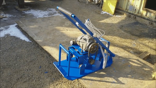
Appearance homemade compactors after final assembly and painting - how to build such a machine, read on
Consider what compactors manufacturing instructions for laying paving slabs. Price of factory equipment with similar characteristics starts from 50 thousand. rubles. So I am sure that the assumptions on guide will be of interest to many.
To seal the bedding sand to a depth of at least 20 cm, ready unit must weigh at least 80 kg. If the weight of the structure will be less, the rammer will be difficult to hold, but the desired effect on the ground it will not.
For transportation of equipment weighing 80 kg or more it will be possible to adapt the car trailer.
Materials and tools
For the manufacture of tamping required welding machine, a Bulgarian with cutting discs for metal, drill with a set of drill bits, clamps, sledge hammer, a measuring instrument. List of materials and components listed in the following table:
| Materials and components | Description |
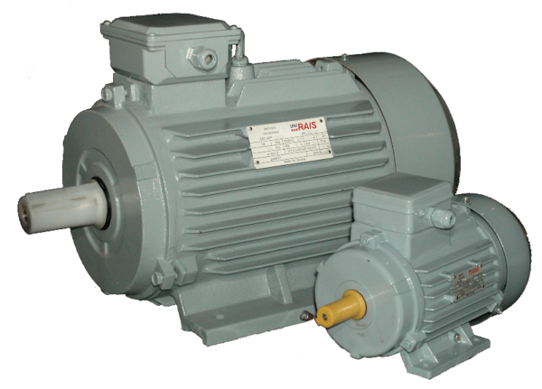 |
electric motor. Recommended engine power should be 1.5-2 kW at 4000-5000 rpm. Engines with less power will not provide the desired rotational speed, and hence the vibratory force will not be enough intense. |
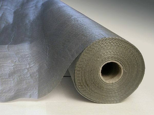 |
Residual current device (RCD). During extended operation homemade tamped parts circuitry may overheat. To eliminate the combustion or melting of the winding insulation to install RCDs or at least a common network circuit breaker (automatic). |
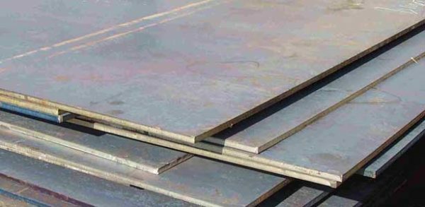 |
Sheet steel with a thickness of 5 mm, 8 mm and 10 mm. Sheet metal with the greatest thickness will need to make a sole cargo and eccentric. Metal smaller thickness required for the manufacture of a site for installation of the motor. |
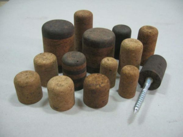 |
removable pulleys. The pulleys are needed to transmit torque from the motor shaft to the shaft of the vibrator. To make the shaft of the vibrator to spin fast pulley on the engine must be three times larger in diameter than the pulley on the shaft. |
 |
Belt, timing can be automobile belt. Belt drive is needed in order to connect the pulleys on the shafts. |
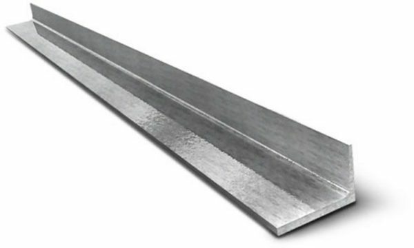 |
Steel Area shelves 5 and a width of 10 cm and a thickness of 10 mm of metal. Corner is needed in order to strengthen the construction of ram in those places where it is impossible to apply this profile pipes. |
 |
A rectangular steel tube 50 × 20 mm. Metal pipe is useful for motor frame assembly and for the assembly of the handle, for which the entire structure can be moved back and forth. |
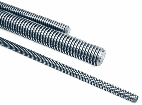 |
The threaded rod with 20 mm diameter and a nut under it. Studs and nuts need to connect the components. |
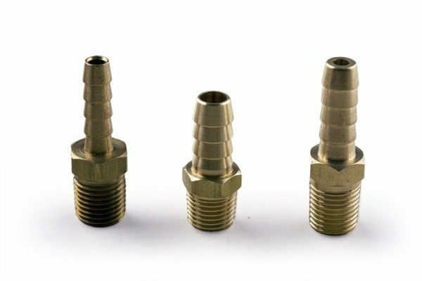 |
sealed bearings. To assemble the shaft hub will need two closed needle bearings. If no needle roller bearings, ball bearings can be used, but they are less durable. Additionally, you will need a pipe with an inner diameter equal to the outer diameter of the bearing. |
 |
A cylindrical steel rod having a diameter of not less than 30 mm. Rod is needed to manufacture the shaft on which the goods will be assigned. |
Assembling tamping
Note that the motor will be used as a drive. But likewise, in the assembled structure may be mounted internal combustion engine. The fact that the setup of electric motors and internal combustion engines is the same, since the motor is attached to the site several bolts.
| Illustration | Description stage |
 |
Fastening ballast shaft. In order for the device to vibrate, to one side of the shaft is welded pack of three - four metal plates. To change the number plates can be drilled in the cylinder shaft through holes. Similar holes are drilled in the plates, which are fastened to the shaft by means of bolts and nuts. |
 |
The blank parts for the attachment of the shaft. Gon harvested two pieces of 10 cm long. and two hubs on the metal casing plates. These guards then vpressuem hub bearings. |
 |
Assembling vibrouzla. Harvested parts collect vibrouzel in which bearings are fixed with threaded shaft therein. On end is attached to the shaft pulley. |
 |
Making a frame and a platform for mounting the motor. From the profile pipe is welded to an external frame perimeter 40 × 60 cm. Sheet steel 8mm thick plate cut to 40 × 50 cm. On the plate, as shown in the photo, the recesses are cut by adjusting bolts and welded loop. |
 |
hinge assembly. In contrast to the plate welded rings, welds on the frame response of the ring, so that their positions coincided. |
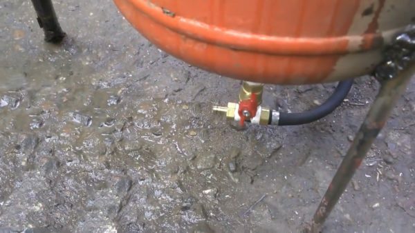 |
Assembling the entire site. Prepared by the frame and rotatable plate connect pin through the loops. Given that the structure will vibrate the pin is inserted through the rubber grommets. The opposite side of the frame welded on the vertical stud, which must pass through the slot in the inclined plate. |
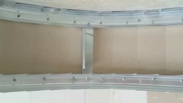 |
Adjust the belt. In order to set an appropriate level of tension the belt on both sides of the plate, through the washer on a vertical stud nuts are screwed. Then, in the amplification of tension, the plate will rise by tightening up the nuts. |
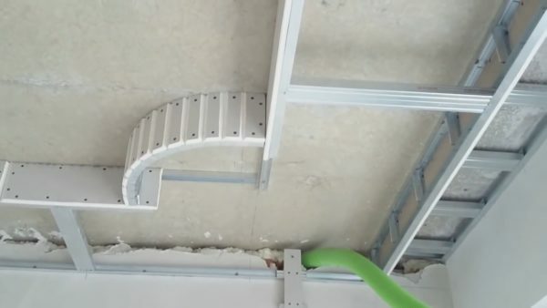 |
Mounting rack under the frame. From each corner of the frame welded on the support 10 cm in length. Of sheet steel 8 mm thick cut reciprocal support to be fastened to the sole plate compactors. Compound of supports will be carried through the elastic rubber pad. |
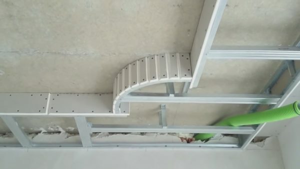 |
Assembling shockmounts. Harvested support and mounting plates, with rubber pads, bolts are tightened. Total should get four dampers - one for each corner of the frame. |
 |
Engine installation and fitting vibrouzla.
|
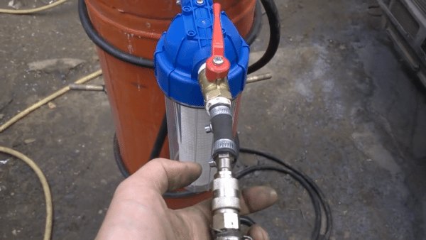 |
Preparations under the sole plate. Sheet of steel 10 mm thick mark up so that they form a rectangle of 40 × 120 cm. By marking made cut rectangle clamps and fastens to the work bench surface. |
 |
Trim corners. At the corners of the plate measured from the prepared 50 mm on each side and connect tags diagonal line to a triangle with a right angle. Grinder cut off each of the four corners of the plate, as shown in the photo. |
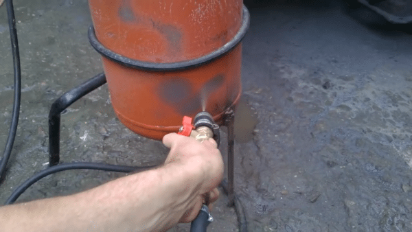 |
Bend the front and rear edge of the plate. From front and rear edges of 100 mm is measured, and this distance is drawn on a line parallel to the edge of the plate. Through the incision depth of approximately 2/3 of the sheet thickness. Make an incision on the leaf Gnehm sledgehammer to get the edge of the ski, as shown in the photo. |
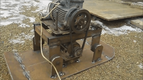 |
The assembly of all the elements. Previously collected structure, including the brackets and the fixing motor frame grab onto the sole of welding. At the same time boil the fold line of the front and rear edge of the sole of the fold. By the way, the folds are needed on both sides of the front and reverse of the machine. |
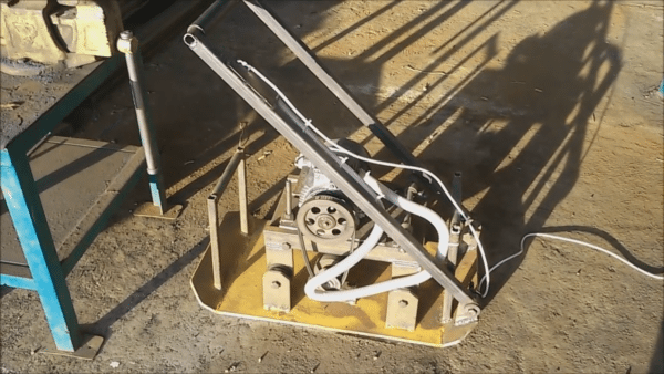 |
Assembly and installation of the handle. At the rear portion of the sole loops are welded to which the handle is attached, welded in the form of the letter "P" of the profile pipe. |
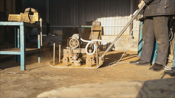 |
Connection and trial run. Power cable through the RCD, is connected to the engine. Vibrator plugged in and performed a trial run. |
In conclusion
Now you know how the vibration plates can be collected with your hands or with a gasoline engine with an electric motor. Also I recommend to watch the video in this article, and if you have any questions, ask them in the comments.