Contents
How to extend the performance of the perforator Bosch
- 3.1 Assembling the rotor of the rotary hammer Bosch 2-26
- 3.2 Installing the stator in the housing
- 3.3 Installing the punch controls
- 4.1 Assembling the intermediate shaft
- 4.2 Assembling the shock shaft assembly
- 4.3 Assembling the mechanical assembly and rotor
- 4.4 Setting the handle switchI modes
- 4.5 assembly quick chuck
- 4.6 Video repair faults perforator Bosch.
For long operation of the Bosch perforator, any regular and timely maintenance, use of quality lubricants, timely replacement of carbon brushes, rubber products are necessary. Monitoring of the condition of bearings and wear of parts. Starting to repair the Bosch perforator with your own hands, it is recommended to use those lubricants that the manufacturer advises.
How to extend the operation of the Bosch
perforator The Bosch perforators require a mandatory technical inspection and maintenance. To properly operate the perforators, you must:
- do not allow dust to enter the cooling holes( you can put on a kapron stocking or use a vacuum cleaner);
- grease drill shanks with special grease;
- does not overheat the power tool( if overheated, the grease crystallizes and stops lubricating the rotating parts);
- for intensive work, replace the rear rotor bearing every 6 months;
after 70 hours to change carbon brushes; - when drilling holes on the ceiling, turn the punch unit down and scroll in this position to transfer the grease back into place;
- after work it is necessary to blow compressed air inside the perforator;
- more often to change a rubber cuff on a cartridge of a perforator;
- do not allow the appearance of arcing on the collector brushes in the idle mode;
- the duration of continuous operation should not exceed a 30-minute interval;
- does not often use the "Strike" mode.
When accepting the repair of the Bosch 2-20, 2-24, 2-26, read the grease card with lubrication points and lubricants.

Bosch
Drill Lubricant Card Bosch Hammers are used to lubricate several types of lubricants, depending on the operating conditions of the components and parts.
Four types of lubricants are used in Bosch hammer drills:
- grease 1615430001- for the reducer and its cavity;
- grease 1615430002- for gears, pendulum bearing, clutch;
- grease 1615430020 - for bearings( FT1V26);
- grease SAE 20 W - for rubber products.
Lubricants differ in viscosity and consistency.
From Russian lubricants it is possible to recommend lubricants under the sonorous name of "Bison":

Domestic lubrication of shanks of drill bits for perforators Bosch
In Bosch perforators 8 bearings are used: three rolling bearings bearing 13,14,67, the bearing of a pendulum( drunk bearing) and four needlep.60.61.62.63.

Schematic diagram of the Bosch 2-26 perforator in the
section Assembling the Bosch rotary hammer 2-26
It is recommended that the perforator is assembled in accordance with the scheme, for example, the Bosch 2-26 perforator. The presence of the assembly scheme simplifies the process, prompts the assembly sequence of parts and assemblies.
The assembly of other Bosch hammers is similar, although some design features in Bosch 2-20, 2-24, 2-26 are available.
Assembling the electrical part of the Bosch 2-26 gun
The assembly of the power tool, including the Bosch 2-26 rotary hammer, should be carried out in a pre-prepared place.
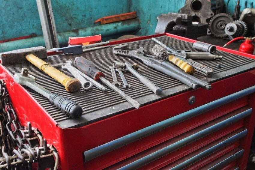
Prepare a workplace by covering the table with clean paper or a napkin. Prepare the tools necessary to carry out the work. From the tools you will need: screwdrivers, pliers, tester, hammer 100 g, spacers of soft metal. Spacers are useful when installing bearings on the rotor and the intermediate shaft of the Bosch perforator, for their attachment.

Schematic diagram of the electrical part of the perforator Bosch 2-26
Assembling the rotor of the rotary hammer Bosch 2-26
On the repaired or new rotor pos.803 install the fan pos. 5, and the bearings pos.13,14.To lubricate the bearings of the rotor, use lubricant 1615430020 from Bosch.
Installing the stator in the
housing The stator installation pos.2 in the body pos. 801 starts with passing through the housing of the connecting wires of the stator coils. The stator in the body is fixed with two screws pos.80.To protect the stator from dust or dirt, a plastic cover pos.
Installing the punch controls for the
In the case of pos. 801, install the Bosch punch switch, pins 19 and the reversing switch board pos.16 in series.make sure that all the lead wires are in the special grooves in the handle of the punch.
Assembling the mechanical part of the Bosch 2-26 gun
Before assembling the mechanical part, check for new rubber seal rings, the integrity of all parts, and the presence of lubricants according to the lubrication chart above.

Scheme of assembling the components of the mechanical unit
Assembling the intermediate shaft
Assembling the intermediate shaft pos.826 begins with installation on the bearing shaft pos.67, the clutch pos 62 and the drunk bearing pos.830.
Toothed sleeve on pos. 823, needle bearing pos. 63, compression spring pos.81, retaining sleeve pos.65.
The intermediate shaft assembly is installed in the inner casing pos. 820 and fixed with a clamp bracket pos. 48.

Intermediate shaft assembly
Assembling the shock shaft assembly
Assembling the shock unit assembly begins with mounting on the shaft of the barrel pos. 8221 of the spur gear cylinder pos.22, the conical spring pos. 80, the locking rings pos.85 and the steel ring pos.38.

The installed gear pos.22 on the shaft of the barrel is fixed with a roller pos.88, not allowing the gear on it to rotate.
On the opposite side, a drummer pos. 847 is assembled into the shaft cavity and a shock piston pos.26 is assembled.

Schematic and assembly order of the Bocsh
Rotary hammer The assembly of the impactor starts with the installation of rubber sealing rings.74.75, scraper pos.71.The assembled drummer is firmly inserted into the cavity of the table.
The assembly of the impact piston starts with the installation of two washers pos. In order to keep the washers in the groove of the piston, grease the surface of the grooves with grease. It remains to install the piston pin pos.29.In the inner cavity of the impact piston, install the pivot of pos. 27 and insert the whole structure inside the cavity of the barrel of the impactor.
The impactor assembly is assembled.

Scheme for assembling the barrel of the perforator's impactor Bosch
The impact shaft and the intermediate shaft should be installed in the inner casing pos. 820.
Assembly of mechanical assembly and rotor
The rotor is attached to the assembled mechanical assembly. The gears of the rotor and the hammer mechanism assembly fit tightly into each other. To install the rotor in the mechanical assembly of the perforator, it is necessary to insert the helical gear of the rotor into the inner case before contact with the helical gear of the intermediate shaft. After assembly, rotate the rotor, checking the smoothness of the scrolling.

Connection of the rotor and shock shaft mechanism
The assembled mechanical assembly is closed with a black plastic cover pos. 819.The cover is fastened with four screws pos.90, with the installation of a sealing rubber ring pos.77.Rubber O-ring must always be lubricated with SAE 20 W grease before installation.
It remains to connect the stator housing( green) to the body of the mechanical unit( black).The housings are connected by four screws.
At the last stage, the carbon brushes pos.811 are installed in the brush holders of the reverse switch pos.16.The button of pos. 4 of the speed regulator is inserted into the handle.
Connect the wires from the stator windings pos.101, 102, the power cable item 806 to the button.
Turn the impactor shaft( first manually and then under tension), and make sure that the rotor rotates smoothly, and the brushes do not interfere with its movement, evenly touching the collector sipes. Sparks near the brushes do not have a tail, but evenly spark through the entire width of the working part.
It remained to close the cover pos. 41 with two screws pos.77.
Setting the mode switch knob
To install the mode switch knob pos.832, the Bosch 2-26 rotary hammer should be placed on the side.

Setting the mode switch
The assembled mode dial of pos. 83 is mounted in the hammer housing so that the red knob button is parallel to the handle of the punch.
The handle rotates clockwise to the "drilling" position. There will be a characteristic click. The handle of the puncher is inserted.
Be sure to check the operation of the mode switch by turning it to the desired position and including the puncher in each mode.
Assembling the
quick-release chuck The Bosch hammers use the SDS-plus cartridge.
Structurally, they differ in the clamping device of working elements.
The assembly of cartridges of the perforator is made after repair of the cartridge, replacement of the destroyed part.
Before assembling the cartridge, it is absolutely necessary to check the fixation balls. They should be free from corrosion, and their diameter should not differ from the nominal by more than 0.01 mm.
The assembly sequence of the quick-release chuck has been described on our website more than once.
The quality of the assembly of a quick-release chuck is determined by its operability. Insert any tool with a suitable shank into the puncher holder. Keeping your hand on the body of the drill, try to pull it out of the cartridge with the weight. If you do not succeed, the patron's work is considered reliable.
That's all. The Bosch 2-26 perforator is assembled. The assembly of the Bosch 2-20, 2-24 rotary hammers is practically the same with the exception of small parts that do not affect the assembly process.


