DC stepper motors are widely used in computer numerical control machines and robotics. The main difference between this electric motor is the principle of its operation. The shaft of the stepper motor does not rotate for a long time, but only rotates through a certain angle. This ensures precise positioning of the working element in space. The power supply of such a motor is discrete, that is, it is carried out by pulses. These impulses turn the shaft at a certain angle, each such turn is called a step, hence the name. Often, these motors work in tandem with a gearbox to improve the setting accuracy and torque on the shaft, and with an encoder to track the shaft position at the moment. These elements are needed to transfer and transform the angle of rotation. In this article we will tell the readers of the site Electrician himself about the device, the principle of operation and the purpose of stepper motors.
Content:
- How a stepper motor works
- Operating principle
- Types and types by polarity or type of windings
- Motor types by rotor design
- Stepper motor control
- Advantages and disadvantages of stepper motors
How a stepper motor works
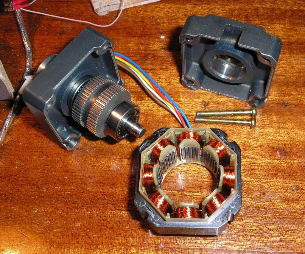
By its type, it is a brushless synchronous motor. Comprises stator and rotor. On the rotor, there are usually sections made of electrical steel sheets (in the photo this is the "toothed" part), and these, in turn, are separated by permanent magnets. The windings are located on the stator, in the form of separate coils.
Operating principle
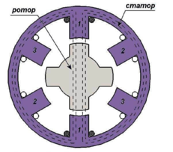
How a stepper motor works can be seen on a conditional model. In position 1, a voltage of a certain polarity is applied to windings A and B. As a result, an electromagnetic field is generated in the stator. Since different magnetic poles are attracted, the rotor will take its position along the axis of the magnetic field. Moreover, the magnetic field of the motor will prevent attempts to change the position of the rotor from the outside. In simple terms, the stator's magnetic field will work to keep the rotor from changing a given position (for example, under mechanical stress on the shaft).
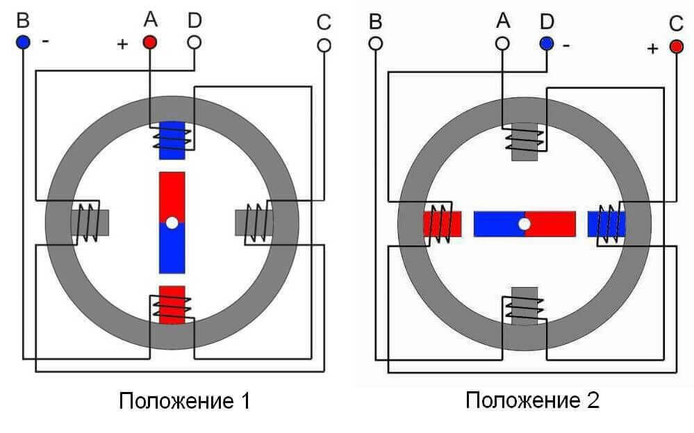
If a voltage of the same polarity is applied to windings D and C, the electromagnetic field will shift. This will cause the permanent magnet rotor to turn to position 2. In this case, the rotation angle is 90 °. This angle will be the step of turning the rotor.

Position 3 is achieved by applying reverse polarity voltage to windings A and B. In this case, the electromagnetic field will be opposite to position 1, the rotor of the motors will be displaced, and the total angle will be 180 °.
When a voltage of reverse polarity is applied to windings D and C, the rotor will rotate through an angle of up to 270 ° relative to the starting position. When a positive voltage is connected to windings A and B, the rotor will take its original position - it will complete a 360 ° revolution. It should be borne in mind that the movement of the rotor occurs along the shortest path, that is, from position 1 to position 4 clockwise the rotor will turn only after passing intermediate 2 and 3 provisions. When connecting the windings after position 1, immediately to position 4, the rotor will turn counterclockwise.
Types and types by polarity or type of windings
Stepper motors use bipolar and unipolar windings. The principle of operation was considered on the basis of a bipolar machine. This design provides for the use of different phases to power the windings. The circuit is very complex and requires expensive and powerful control boards.
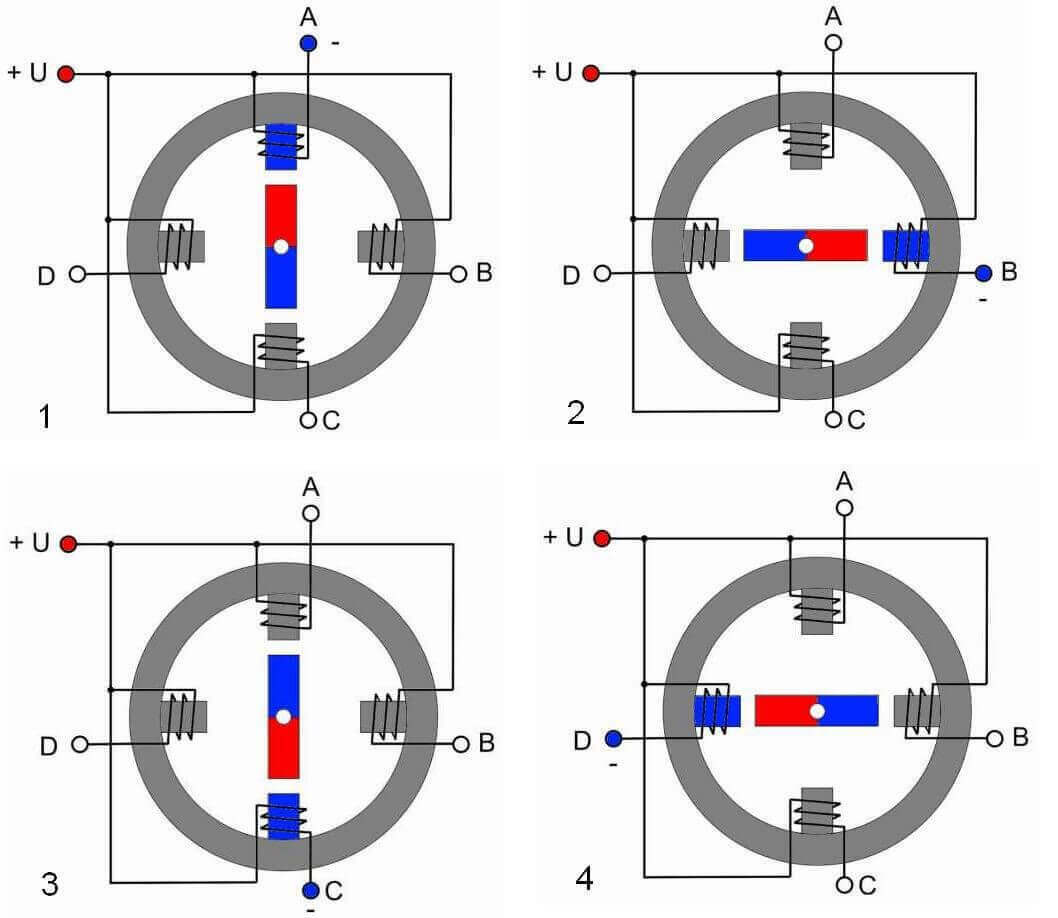
A simpler control scheme in unipolar machines. In such a scheme, the beginning of the windings are connected to a common "plus". On the second conclusions of the windings, "minus" is alternately supplied. This ensures the rotation of the rotor.
Bipolar stepper motors are more powerful, they have 40% more torque than unipolar ones. Unipolar electric motors are much more convenient to operate.
Motor types by rotor design
According to the type of rotor design, stepper motors are divided into machines:
- with a permanent magnet;
- with variable reluctance;
- hybrid.
SM with permanent magnets on the rotor is designed in the same way as in the examples discussed above. The only difference is that there are much more magnets in real machines. They are usually distributed on a shared disk. The number of poles in modern motors reaches 48. One step in such electric motors is 7.5 °.
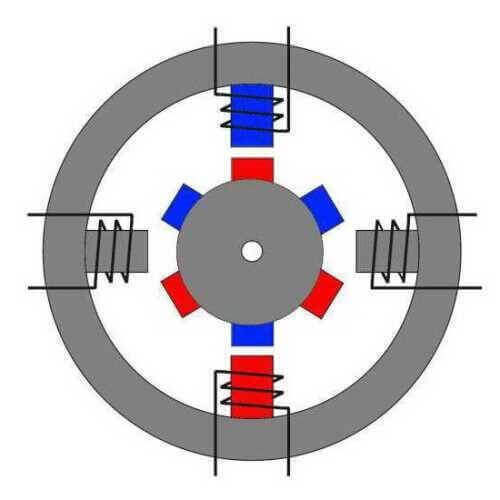
Variable reluctance motors. The rotor of these machines is made of soft magnetic alloys, they are also called "reactive stepping motor". The rotor is assembled from individual plates and looks like a gear wheel in section. Such a design is necessary so that the magnetic flux is closed through the teeth. The main advantage of this design is the absence of a locking torque. The fact is that the permanent magnet rotor is attracted to the metal parts of the electric motor. And it is quite difficult to turn the shaft in the absence of voltage on the stator. There is no such problem in a stepper motor with variable reluctance. However, a significant disadvantage is the small torque. The pitch of these machines is usually between 5 ° and 15 °.
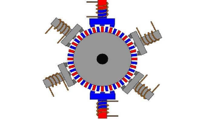
The hybrid stepper motor was developed to combine the best characteristics of the two previous types. These motors have a small pitch ranging from 0.9 to 5 °, and have high torque and holding capacity. The most important plus is the high accuracy of the device. Such electric motors are used in the most modern high-precision equipment. The disadvantages include only their high cost. Structurally, the rotor of this device is a magnetized cylinder on which soft magnetic teeth are located.
For example, a 200-step stepper motor uses two toothed discs with 50 teeth each. The discs are offset relative to each other by a half-tooth so that the cavity of the positive pole coincides with the protrusion of the negative pole and vice versa. Thanks to this, the rotor has 100 poles with reverse polarity.
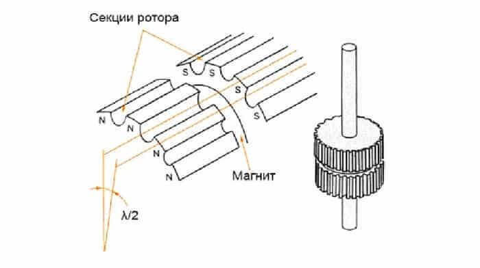
That is, both the south and north poles can be displaced relative to the stator in 50 different positions, and in total 100. And a phase shift by a quarter gives another 100 positions, this is done due to sequential excitation.
Stepper motor control
Management is carried out by the following methods:
- Wave. In this method, voltage is applied to only one coil, to which the rotor is attracted. Since only one winding is involved, the rotor torque is small and not suitable for high power transmission.
- Full step. In this embodiment, two windings are excited at once, thereby ensuring the maximum torque.
- Semi-step. Combines the first two methods. In this embodiment, the voltage is applied first to one of the windings, and then to two. In this way, more steps are realized, and the maximum holding force, which stops the rotor at high speeds.
- Microstepping control is performed by applying microstep impulses. This method ensures smooth rotation of the rotor and reduces jerking during operation.
Advantages and disadvantages of stepper motors
The advantages of this type of electrical machines include:
- high speeds of starting, stopping, reverse;
- the shaft is rotated in accordance with the command of the control device at a predetermined angle;
- clear fixation of the position after stopping;
- high positioning accuracy, without strict requirements for the presence of feedback;
- high reliability due to the absence of a collector;
- maintaining maximum torque at low speeds.
Disadvantages:
- possible violation of positioning when the mechanical load on the shaft is higher than the permissible for a particular motor model;
- resonance probability;
- complex control scheme;
- low rotation speed, but this cannot be attributed to significant disadvantages, since stepper motors are not used to simply rotate something like brushless, for example, but for positioning mechanisms.
A stepper motor is also called a "finite number of rotor positions" motor. This is the most capacious and at the same time concise definition of such electric machines. They are actively used in CNC machines, 3D printers and robots. The main competitor of the stepper motor is servo, but each of them has its own advantages and disadvantages, which determine the appropriateness of using one or the other in each case.
Related materials:
- What are the types of electric motors and how they differ
- What is step voltage and how dangerous it is
- What is a synchronous motor and where is it used

