Content
- Two-gang switch design
- General wiring diagram
- Device Connection Procedure
Installation and connection of a two-key light switch is relevant in cases where it may occur the need to change the intensity of the lighting of the room or control the illumination of various zones the interior. You can adjust the amount of light by changing the number of working fixtures using such a device. Since this product has two keys, it is able to control the operation of two groups of lamps. As a rule, two-gang light switches are installed in conjunction with chandeliers with more than two bulbs.

Another situation in which the use of such devices is preferable is their use for switching on from one place of light in different rooms or corridors.
It must be said right away that the wiring diagram for the two-gang switch is in many ways similar to the similar circuit used for installation of single-key models.
Thus, the scope of such devices is very extensive, but in all cases the same connection scheme is used. In order to figure out how to connect a two-key switch, you should familiarize yourself with its device and the principle of operation.
Two-gang switch design
The classification of these devices is quite simple. There are embedded and overhead models designed for use, respectively, with hidden or open wiring. Among the additional functions that these devices can be equipped with, one can highlight the backlight. Switches equipped with lights are easy to find in a dark room, so they are very convenient to use.
The design of the two-gang product is quite simple and in many ways similar to the internal structure of a single switch. The only difference is that there is a separate contact, designed to power the second group of consumers. Structurally, a two-button switch consists of the following main elements:
- Working part. Unlike single-key models with two terminals, such a switch is equipped with three contacts. One of them is incoming and two are outgoing. The lead-in contact is designed to connect to it a phase wire coming from the junction box. Outgoing contacts of the working part are used to connect wires to them, which are used to power consumers. As a rule, a marking is applied to the case of the working part of the switch, which facilitates the determination of the type of each terminal. This part of the design of the device must be installed so that the common terminal is located at the bottom.
HELPFUL INFORMATION:Connecting the passage switch

- Decorative frame.
- Two keys (can be equipped with windows for backlighting).

If the design of the device provides for backlighting, then it includes a small electrical circuit, which includes an LED (or neon lamp), a resistor, and sometimes a capacitor. This electrical circuit is connected to the contacts of the switch. The principle of its work is quite simple. Since the current-limiting resistor has a sufficiently large resistance, then when it is short-circuited by the switched contacts of the switch, the current does not flow in the backlight circuit. When the working contacts open, a small current, limited by the resistance of the resistor, flows in the backlight circuit, providing LED burning.
Backlit switches are very common today.
General wiring diagram
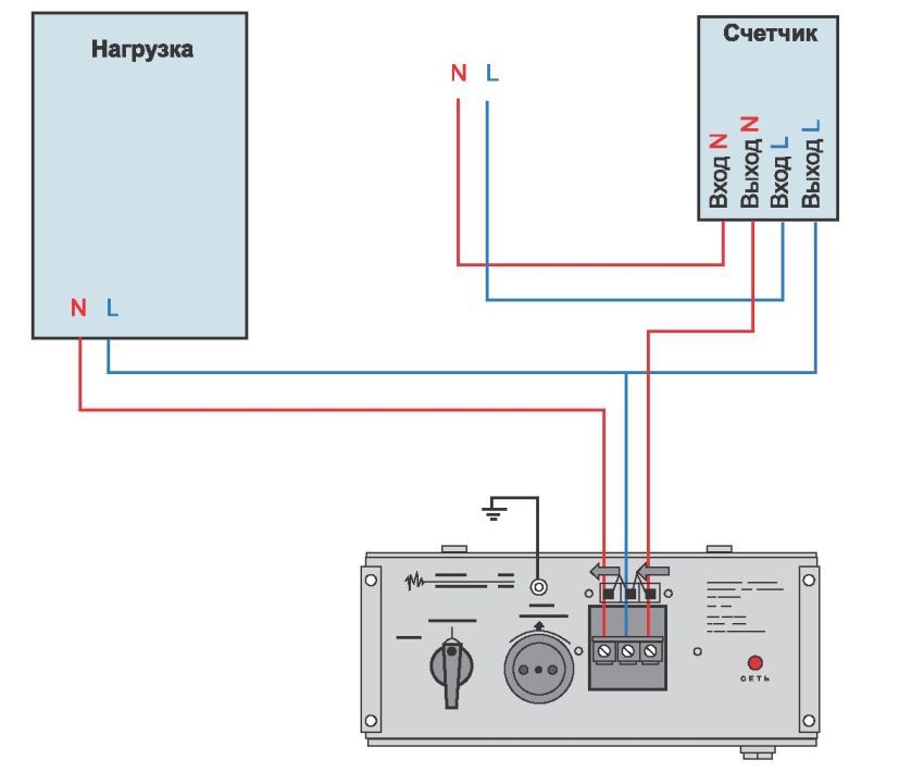
The connection diagram of the two-key light switch is shown in the figure.

The ground wire, which is shown in the figure, is present in the wiring of far from all buildings. If for connecting powerful household appliances such as a hob or washing machine, they Because they try to ground at least the shield of an electric meter, grounding in lighting circuits is usually missing. To increase the safety of using wiring in such conditions, it makes sense to install at the entrance to the apartment residual current circuit breakers or differential automaton.
The connection diagram of the double circuit breaker shown in the figure has two separate lamps as a load, but often this connection is used to control each switch key with a chain of several series-connected light bulbs.
Device Connection Procedure
HELPFUL INFORMATION:At what height should sockets and switches be installed?
The main rule that must be observed during the installation of all switching devices is the need to install them in such a way that when disconnected, the phase wire circuit breaks. This should be done, first of all, so that when replacing the light bulb, it was enough just to turn off the switch without resorting to the use of an input machine.
The fact is that a large number of cases of electric shock to a person occurs precisely when performing such work. Such cases, unfortunately, often take place, despite the fact that for a dangerous situation to arise not only mix up the wire on which the switch should be installed, but also incorrectly connect the electrical cartridge light bulbs.
As for working with any elements of electrical wiring, when installing and connecting two-gang switches, adhere to safety regulations, the main of which is the need to turn off the voltage for a while performance of work. Since the junction boxes are in most cases located at a height, an important element when working with them is the use of a reliable stepladder or stand.
In order to properly install such a device, you must adhere to the following procedure:
- With the help of an input machine, the power supply to the apartment is turned off. This can also be done using the machine, which is responsible for the group of consumers, which includes the necessary lighting circuit.
- The junction box contains wires coming from consumers that need to be connected to the network, phase and zero from the input panel, as well as three wires coming from the switch. Please note that if it is necessary to connect copper and aluminum wires, terminal blocks must be used. This situation arises quite often in houses of the old building, where the internal wiring was carried out with an aluminum wire.
- All zero conductors in the box are interconnected.
- The phase wire going from the entrance to the apartment is connected to the conductor, which will be connected to the input terminal of the two-key light switch.
- Each of the phase wires used to power individual consumers is connected to the corresponding output wire of the circuit breaker.
- All joints are well insulated. To perform the insulation of the joints in the junction box, it is preferable to use fiberglass tape, as one of the most resistant to temperature influences.
- The keys are removed from the switch, after which the working part is disconnected from the frame.
- Corresponding wires are connected to the contacts of the working part. For convenience, it is advisable to use cables whose cores have a different color marking. If the design of the device provides for backlighting, then the contacts of its circuitry are connected to the terminals of the switch.
- With the help of sliding legs, the working part is installed in the socket. It is important to ensure that the on position of the device corresponds to pressing the top of its keys.
- Using special grooves or bolts, a decorative frame is mounted.
- The keys are installed.
HELPFUL INFORMATION:Installation of a single-key switch
In practice, connecting a double switch is not much more difficult than connecting a single-key device.